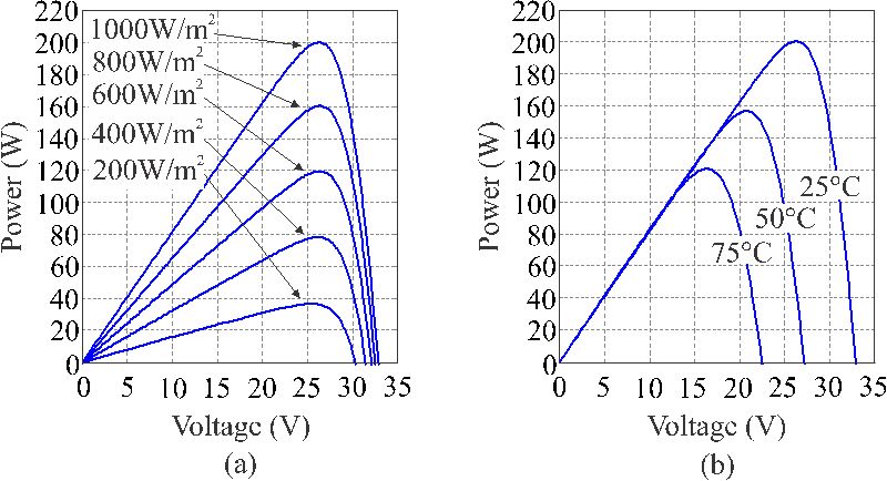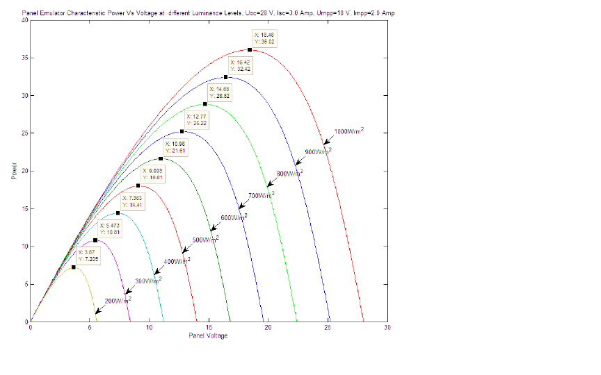
 The V-I characteistic of PV Emulator is shown as such in the manual(see attachment). Here the voltage varies a lot with irradiation while current not so much. But in reality it is supposed to be the opposite ! Is the VI characteristics wrong ?

-
Ask a related question
What is a related question?A related question is a question created from another question. When the related question is created, it will be automatically linked to the original question.