This thread has been locked.

If you have a related question, please click the "Ask a related question" button in the top right corner. The newly created question will be automatically linked to this question.

Problem with custom PCB of the DRV8301-69M-Kit

Other Parts Discussed in Thread: DRV8301-69M-KIT, DRV8301

Hello,

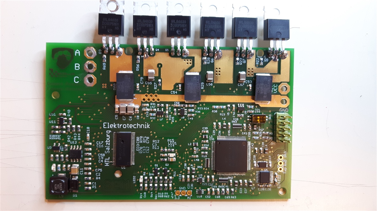
for our project of an electrically powered vehicle, we designed a PCB based on the schemetatics of the reference design "DRV8301-69M-Kit". For this reason, we decided to combine the schematics of the ControlCard and the BoosterPack in one PCB. We used exactly the same components as mentioned in the BOM, the only differences regard the types of MOSFETs, since we needed a TO-220 package, and the voltage division to measure the bus voltage (VDCBUS), which was unintended because we forgot to implement it.

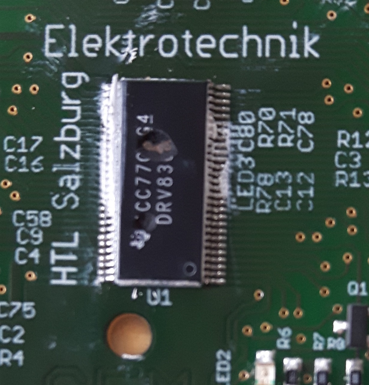
During the first test, we slowly increased the supply voltage to 48V and the current consumption was about 20mA. Not having connected any load, we managed to run an example program successfully. The temperature of the DRV8301 increased noticeably and the current rose to about 110mA. Also, we could measure an AC voltage at the outputs for the motor. Afterwards, we also tested  to switch on the power supply without a delay to the 48V several times, which worked as well. The next step was to connect a PMSM, which could be identified by the identification routine in the GUI successfully. Somethimes, though, when we tried to run the motor, the connection the the MC was cut, but sometimes worked again after reconnect. After some time, we tried again with the example project (lab04a), but shortly after clicking the execute-button in CCS, the DRV8301 blew up. We've tested this scenario with two different PCBs, which always resulted in the same problem. In both cases, the explosion holes of the DRV8301 appeared at the same position.

Since we were working with example projects, we can exclude a cause by the software.What could these explosions of the DRV8301 be due to? Are there any protection mechanisms for the DRV8301 that might be faulty?

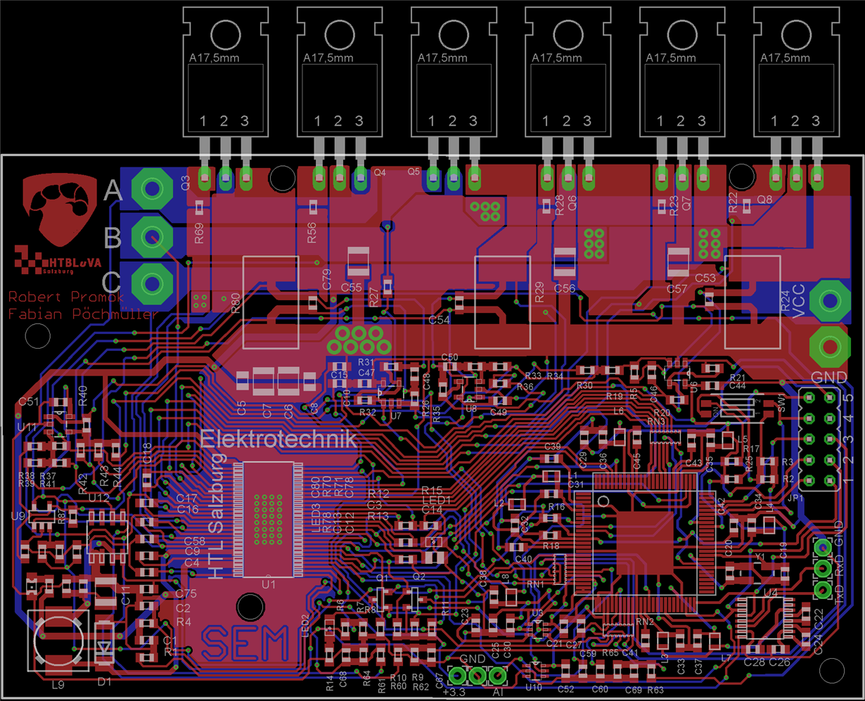
Please find a picture of our layout with the damaged DRV8301 enclosed.

Thank you for any help in advance!

Regards

  • Hi Lukas,

    First impressions based on what I see and what I might recommend investigating:
    1) you mention that "the connection to the MC was cut" - I assume this means that the GUI/CCS disconnects?  If so, then EMI is likely causing issues for this.  I might recommend putting an EMI bead on the USB cable.  I might also recommend using an isolated emulator to connect to the C2000 device - if you want to debug via JTAG while the motor is running.  Or add in something like the TMDSADP1414-ISO to improve the debugger connection.
    2) Your trace/component clearances in certain places - like between the "VCC" and "GND" connectors - seem very tight.  As you're connecting things up, make completely sure that you're not creating shorts.
    3) I do not see any major bus capacitance on the DCbus.  Note that if you are applying torque to slow down the motor, the DCbus voltage will rise.  Vbus on the board may then get sufficiently high to damage the inverter circuitry.  Bus capacitance helps this - to some extent.  Another factor in this involves the power supply that is generating the DCbus. I might recommend monitoring the bus voltage during operation.
    4) Your decoupling/etc caps for the DRV chip seem to be a good distance from the DRV chip - this can reduce performance to some extent, but I doubt it's the root cause of your issue


    Thank you,
    Brett

  • Hello Brett,

    thank you for your answer. We've now added a bus capacitance and managed to establish a quite reliable USB connection to the board. However, in few cases we still get disconnected, but mainly because of high current consumption during identify and the resulting undervoltage. Now we're trying to fix this issue by adding a higher capacitance to the intermediate circuit. We're using using an external custom-made programmer with isolated connectors and four of the ISO-7221 IC.

    Unfortunately, we're now facing yet another problem. Our modified example program which works quite well on the reference design but not on our self-build board. We think that this problem might be due to the different MOSFETs that we used, although the R_ds value is almost the same (SUM110N06-3m4L: R_ds_typical = 2.8mOhms at Vgs = 10V vs. our MOSFETS IRLB4030 R_ds_typical = 3,4 mOhms at Vgs = 10V).

    Do we have to change the Rds values in the DRV or are they identified automatically? Is is also important that the gate threshold voltage has to be exactly the same as the original MOSFETs?

    Another issue that has occured is that the motor makes a high-frequence noise with our self-made board and the same project that worked well on the reference design. Do you know what could be the reason for that?

    Thank you and best regards,

    Lukas.

  • Lukas,

    It is my understanding that re-running Motor ID on the new board will resolve any minor hardware changes to the overall design.  Your change to a different set of FETs shouldn't be a problem.

    Your high-frequency noise likely either comes from [A] something wrong with configuration (something like motor ID) or [B] some kind of problem in layout.


    Thank you,
    Brett


  • Hi Lukas,

    The gate voltage and Vds trip point should not have a large effect.

    The main concern would be if their were big differences in the gate charge of the MOSFETs. This could lead to much faster switching speeds even when using the same gate drive setup. Faster switching speeds can lead to more noise in the system and over/undershoot voltages.

    This would not explain the high-frequency noise though.

    I would recommend take a look at some of the MOSFET gate and switch node voltages and comparing between the two designs.

  • reason of high frequency noise---->If you are using pwm frequency less than 20khz then noise is audible.So,increase it above 20khz.I think it would work because i solved this problem of my motor this way.
  • Thank you for sharing the additional information!

    Elizabeth