This thread has been locked.

If you have a related question, please click the "Ask a related question" button in the top right corner. The newly created question will be automatically linked to this question.

120cycles Interrupt latency on 28035

Hi,


I have a PWM interrupt with 100 kHz and for debugging I toggle a GPIO at begin of the ISR. On the Oszi I observe a maximal jitter of 2 us (120 cycles).


The maximal jitter depends definitely on the code of the main loop.
This long Interrupt latency seems to be caused by a for-loop where 64 register are copied. If I split the for-loop into two for-loops the ISR latency is reduced to the half. (See sample code).

void main(void) {
	...
	unsigned reg1[64], reg2[64];

	while(1) {
	
	....

		set GPIO Y
#if 1
		// cause 2 us Interrupt latency 
		for(int i = 0; i < 64; i++) {
			reg1[i] = reg2[i];
		}
#else
		// cause 1 us Interrupt latency 
		for(int i = 0; i < 32; i++) {
			reg1[i] = reg2[i];
		}
		for(int i = 32; i < 64; i++) {
			reg1[i] = reg2[i];
		}
#endif
	clear GPIO Y
	}
}


void isr_pwm(void){
	toggle GPIO X

}


Is it possible that a for-loop stall the ISR?

-    No disabled ISR
-    No nested ISR
-    All code is in the ram.
-    Maybe stack and the code in the same physical memory block

  • Be sure other ISRs are disabled.
  • Hi,

    no there is no other ISR enabled.

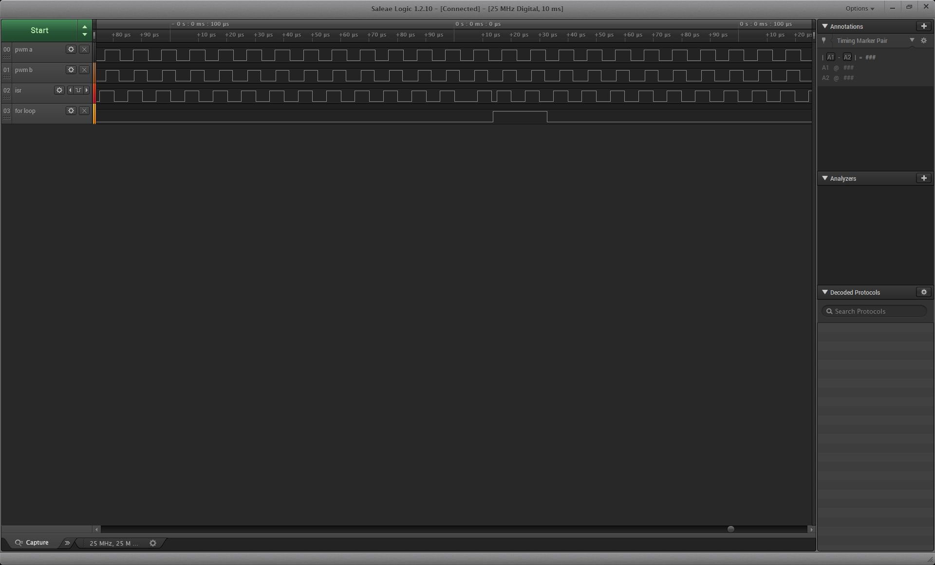
    I also see on the scope that the for-loop block the ISR (GPIOs).
    Addition the maximal jitter is much lees, if I split the loop.

    -Thomas
  • It' s not reasonable.

    you can program code into flash, and all breakpoints should be removed.

  • Tom Tom84,

    I notice your ISR is declared without the "interrupt" keyword.  Are you using TI-RTOS in your system?

    Regards,

    Richard

  • Hi Richard,

    I just forgot the keyword in the example /pseudo-code.
    In my project, I use the keyword __interrupt. No, I don't use TI-RTOS.

    -Thomas
  • Hi,


    I just modified the epwm_updown Example and I do observe the same behavior. Below there is a capture of GPIO 0-3 and the C code.

    Please help me.

    Thomas

    Here is the code:

    //###########################################################################
    // Description:
    //! \addtogroup f2803x_example_list
    //! <h1>ePWM Action Qualifier Module using up/down count (epwm_updown_aq)</h1>
    //!
    //! This example configures ePWM1, ePWM2, ePWM3 to produce an waveform with
    //! independent modulation on EPWMxA and EPWMxB. The compare values CMPA
    //! and CMPB are modified within the ePWM's ISR. The TB counter is in up/down
    //! count mode for this example.
    //!
    //! Monitor ePWM1-ePWM3 pins on an oscilloscope as described
    //!
    //! \b External \b Connections \n
    //!  - EPWM1A is on GPIO0
    //!  - EPWM1B is on GPIO1
    //!  - EPWM2A is on GPIO2
    //!  - EPWM2B is on GPIO3
    //!  - EPWM3A is on GPIO4
    //!  - EPWM3B is on GPIO5
    //
    //###########################################################################
    // $TI Release: F2803x C/C++ Header Files and Peripheral Examples V130 $
    // $Release Date: May  8, 2015 $
    // $Copyright: Copyright (C) 2009-2015 Texas Instruments Incorporated -
    //             http://www.ti.com/ ALL RIGHTS RESERVED $
    //###########################################################################
    
    #include "DSP28x_Project.h"     // Device Headerfile and Examples Include File
    
    volatile int isr_delay = 0;
    volatile unsigned reg1[128], reg2[64];
    
    // Prototype statements for functions found within this file.
    void InitEPwm1Example(void);
    __interrupt void epwm1_isr(void);
    
    
    // Configure the period for each timer
    #define EPWM1_TIMER_TBPRD  300 // Period register


    /**
     * Initialize PIN function
     * - Set PIN MUX (PIN function) e.g. SPI XX, GPIO
     * - Configure direction of GPIO (input or output)
     * - Set GPIO Output state
     */
    void InitGpio(void) {
        EALLOW;
    
    //--------------------------------------------------------------------------------------
    //  GPIO-02 - PIN FUNCTION = PWM2A
    	GpioCtrlRegs.GPAMUX1.bit.GPIO2 = 0;		// 0=GPIO,  1=EPWM2A,  2=Resv,  3=Resv
    	GpioCtrlRegs.GPADIR.bit.GPIO2 = 1;		// 1=OUTput,  0=INput
    //	GpioDataRegs.GPACLEAR.bit.GPIO2 = 1;	// uncomment if --> Set Low initially
    //	GpioDataRegs.GPASET.bit.GPIO2 = 1;		// uncomment if --> Set High initially
    //--------------------------------------------------------------------------------------
    //  GPIO-03 - PIN FUNCTION = PWM2B
    	GpioCtrlRegs.GPAMUX1.bit.GPIO3 = 0;		// 0=GPIO,  1=EPWM2B,  2=SPISOMI-A,  3=COMP2OUT
    	GpioCtrlRegs.GPADIR.bit.GPIO3 = 1;		// 1=OUTput,  0=INput
    //	GpioDataRegs.GPACLEAR.bit.GPIO3 = 1;	// uncomment if --> Set Low initially
    //	GpioDataRegs.GPASET.bit.GPIO3 = 1;		// uncomment if --> Set High initially
    //--------------------------------------------------------------------------------------
    }
    
    void main(void)
    {
    	int i, cnt = 0;
    // Step 1. Initialize System Control:
    // PLL, WatchDog, enable Peripheral Clocks
    // This example function is found in the DSP2803x_SysCtrl.c file.
       InitSysCtrl();
    
    // Step 2. Initialize GPIO:
    // This example function is found in the DSP2803x_Gpio.c file and
    // illustrates how to set the GPIO to it's default state.
       InitGpio();
    
    // For this case just init GPIO pins for ePWM1, ePWM2, ePWM3
    // These functions are in the DSP2803x_EPwm.c file
       InitEPwm1Gpio();
    
    
    // Step 3. Clear all interrupts and initialize PIE vector table:
    // Disable CPU interrupts
       DINT;
    
    // Initialize the PIE control registers to their default state.
    // The default state is all PIE interrupts disabled and flags
    // are cleared.
    // This function is found in the DSP2803x_PieCtrl.c file.
       InitPieCtrl();
    
    // Disable CPU interrupts and clear all CPU interrupt flags:
       IER = 0x0000;
       IFR = 0x0000;
    
    // Initialize the PIE vector table with pointers to the shell Interrupt
    // Service Routines (ISR).
    // This will populate the entire table, even if the interrupt
    // is not used in this example.  This is useful for debug purposes.
    // The shell ISR routines are found in DSP2803x_DefaultIsr.c.
    // This function is found in DSP2803x_PieVect.c.
       InitPieVectTable();
    
    // Interrupts that are used in this example are re-mapped to
    // ISR functions found within this file.
       EALLOW;  // This is needed to write to EALLOW protected registers
       PieVectTable.EPWM1_INT = &epwm1_isr;
       EDIS;    // This is needed to disable write to EALLOW protected registers
    
    // Step 4. Initialize all the Device Peripherals:
    // Not required for this example
    
    // For this example, only initialize the ePWM
       EALLOW;
       SysCtrlRegs.PCLKCR0.bit.TBCLKSYNC = 0;
       EDIS;
    
       InitEPwm1Example();
    
       EALLOW;
       SysCtrlRegs.PCLKCR0.bit.TBCLKSYNC = 1;
       EDIS;
    
    // Step 5. User specific code, enable interrupts:
    
    // Enable CPU INT3 which is connected to EPWM1-3 INT:
       IER |= M_INT3;
    
    // Enable EPWM INTn in the PIE: Group 3 interrupt 1-3
       PieCtrlRegs.PIEIER3.bit.INTx1 = 1;
    
    // Enable global Interrupts and higher priority real-time debug events:
       EINT;   // Enable Global interrupt INTM
       ERTM;   // Enable Global realtime interrupt DBGM
    
    // Step 6. IDLE loop. Just sit and loop forever (optional):
       for(;;)
       {
    
           __asm("          NOP");
    
    	   GpioDataRegs.GPASET.bit.GPIO3 = 1;
           for (i = 0; i < 64; i++) {
    			reg1[64 + i] = reg2[1];
    		}
           GpioDataRegs.GPACLEAR.bit.GPIO3 = 1;
    
           DELAY_US(1000);
           cnt++;
           DELAY_US(10);
           cnt += 10;
    
           __asm("          NOP");
    
    
           __asm(" RPT #709 || NOP");


       }
    }
    
    
    int isr_cnt = 0;
    __interrupt void epwm1_isr(void) {
    	int i;
    
    	GpioDataRegs.GPASET.bit.GPIO2 = 1;
    	isr_cnt++;
    
    	for(i = 0; i < 50; i++){
    		isr_delay = i;
    	}
    	GpioDataRegs.GPACLEAR.bit.GPIO2 = 1;
    
    	// Clear INT flag for this timer
    	EPwm1Regs.ETCLR.bit.INT = 1;
    
    	// Acknowledge this interrupt to receive more interrupts from group 3
    	PieCtrlRegs.PIEACK.all = PIEACK_GROUP3;
    }
    
    void InitEPwm1Example()
    {
       // Setup TBCLK
       EPwm1Regs.TBPRD = EPWM1_TIMER_TBPRD;           // Set timer period 801 TBCLKs
       EPwm1Regs.TBPHS.half.TBPHS = 0x0000;           // Phase is 0
       EPwm1Regs.TBCTR = 0x0000;                      // Clear counter
    
       // Set Compare values
       EPwm1Regs.CMPA.half.CMPA = EPWM1_TIMER_TBPRD / 2 - 10;     // Set compare A value
       EPwm1Regs.CMPB = EPWM1_TIMER_TBPRD / 2 + 10;              // Set Compare B value
    
       // Setup counter mode
       EPwm1Regs.TBCTL.bit.CTRMODE = TB_COUNT_UPDOWN; // Count up
       EPwm1Regs.TBCTL.bit.PHSEN = TB_DISABLE;        // Disable phase loading
       EPwm1Regs.TBCTL.bit.HSPCLKDIV = TB_DIV1;       // Clock ratio to SYSCLKOUT
       EPwm1Regs.TBCTL.bit.CLKDIV = TB_DIV1;
    
       // Setup shadowing
       EPwm1Regs.CMPCTL.bit.SHDWAMODE = CC_SHADOW;
       EPwm1Regs.CMPCTL.bit.SHDWBMODE = CC_SHADOW;
       EPwm1Regs.CMPCTL.bit.LOADAMODE = CC_CTR_ZERO;  // Load on Zero
       EPwm1Regs.CMPCTL.bit.LOADBMODE = CC_CTR_ZERO;
    
       // Set actions
       EPwm1Regs.AQCTLA.bit.CAU = AQ_SET;             // Set PWM1A on event A, up count
       EPwm1Regs.AQCTLA.bit.CAD = AQ_CLEAR;           // Clear PWM1A on event A, down count
    
       EPwm1Regs.AQCTLB.bit.CBU = AQ_SET;             // Set PWM1B on event B, up count
       EPwm1Regs.AQCTLB.bit.CBD = AQ_CLEAR;           // Clear PWM1B on event B, down count
    
       // Interrupt where we will change the Compare Values
       EPwm1Regs.ETSEL.bit.INTSEL = ET_CTR_ZERO;      // Select INT on Zero event
       EPwm1Regs.ETSEL.bit.INTEN = 1;                 // Enable INT
       EPwm1Regs.ETPS.bit.INTPRD = ET_1ST;            // Generate INT on 3rd event
    }
    
    
    //===========================================================================
    // No more.
    //===========================================================================


  • In the example above __asm(" RPT #709 || NOP"); cause the latency.
    So I can't reproduce the problem.
  • Tom Tom84,

    I notice the following lines in your ISR:

            for(i = 0; i < 50; i++){
                   isr_delay = i;
            }

    Probably they represent an interrupt payload but they are consuming a lot of cycles.  Om my machine with no optimization it takes close to 550 cycles to do this.  A 100kHz interrupt on a 60MHz machine has 600 CPU cycles bandwidth so I wonder if you are getting close to having no CPU overhead.

    Can you try commenting out those lines to see if the problem changes / goes away?

    Regards,

    Richard

  • Yes, this code represent an interrupt payload.
    I use the optimizer (level 2), and with this setting the isr duration is ~300cycles. (Signal 02 isr on the scope capture above.)
    The example proofs that, that the asm nop loop, bocks the isr.

    Is there an overview of blocking statements (e.g. IQmath, loop, direct assembler code)?

    In the meanwhile, I am not so sure anymore, that the for-loop causes the jitter.
    I tried to isolate the problem, and it looks like that there are several reasons which cause the long latency.

    • If I skip a register write in the ISR, then the latency is much less. But I am not sure why: reduce isr payload, or because the array is now only used in the main loop
    • If I due nothing in the main, I latency jitter is almost 0.

    I have found a setting where the jitter is +/-30 cycles, which sounds reasonable. This is a level I can accept.

    At the moment I am quite busy. May I come back later to this topic.