

Hello,
I'm planning to develop a design using the TMS320F28069F processor and I'm looking at how I should go about debugging and programming it with JTAG.
As this will just be a prototype, I'd like to use the hardware that I have on hand already for JTAG - a TMS320F28027F Launchpad and a MSP-EXP432P401R Launchpad. The former has an XDS100v2 programmer attached, but with no pins for debug out use broken out. The latter has the new XDS110-ET onboard, with only the following pins broken out on J103 (The MSP432 board I have is a revision 1.0 board with black silkscreen and white soldermask, different to what appears available for purchase today with red soldermask and later revision):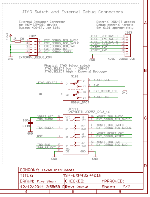
I'd like to be able to use the onboard XDS110 to program and debug my target board from within CCS. From what I can tell, I only have access to the TMS and TCK JTAG lines. The XDS110 allegedly supports JTAG 1149.7 two-wire interface with just these pins, but I am unsure if the target chip supports this - the datasheet only mentions 1149.1 implementation.
My questions are:
Is there a way to use either of the mentioned Launchpad boards to connect via JTAG to my target board?
Does the TMS320F28069F support JTAG 1149.7 two-wire mode? (if yes, I can use the EXP432P401R Launchpad for JTAG)
Does the latest revision of the EXP432P401R have the necessary pins broken out to do what I'd like (and if so, am I guaranteed to get a new revision board if I order one from TI)?
Is there a way to break out the JTAG pins from the XDS100v2 programmer on the F28027 Launchpad?
What connector footprint should I be placing on my custom board for JTAG use (I assume TI compact 20 pin) and are there any wiring references available?

-
Ask a related question
What is a related question?A related question is a question created from another question. When the related question is created, it will be automatically linked to the original question.


