This thread has been locked.

If you have a related question, please click the "Ask a related question" button in the top right corner. The newly created question will be automatically linked to this question.

TMS320F28377S: SCI ISN'T PROPERLY WORKING

Part Number: TMS320F28377S
Other Parts Discussed in Thread: C2000WARE,

Hi !

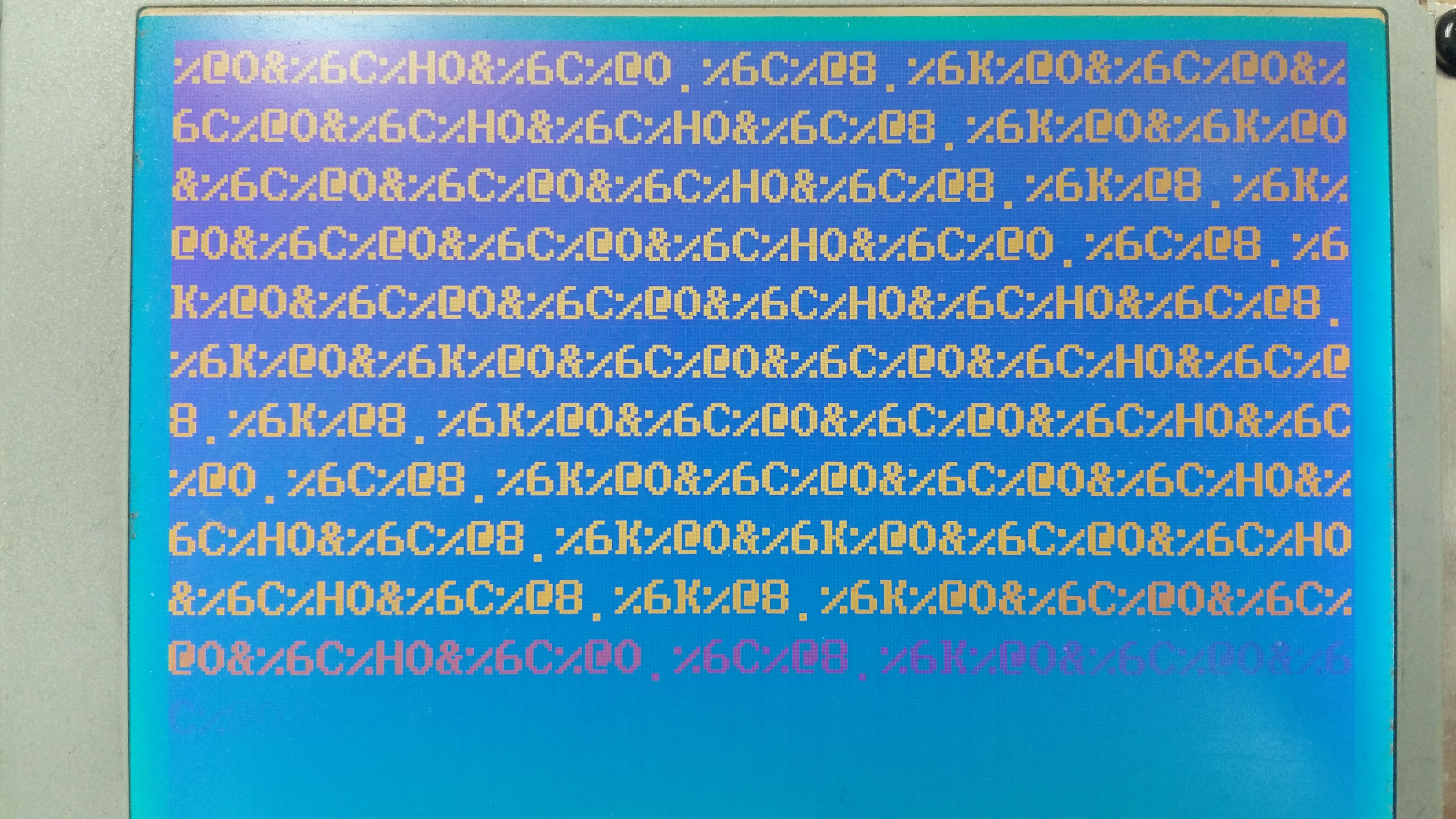
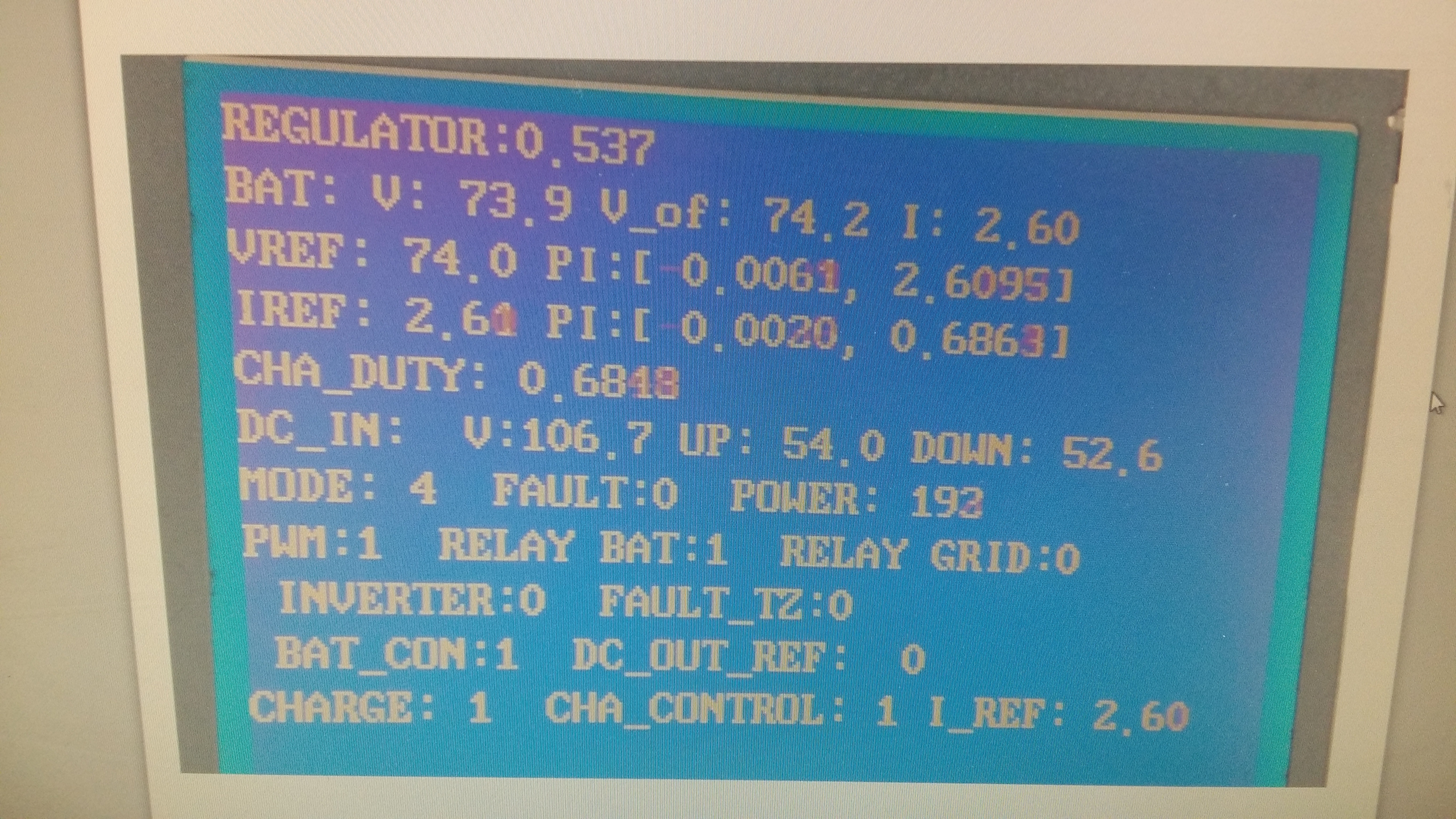
I'm facing to problem that   there is digital signal in SCI gpio out , but in LCD monitor any numbers and values I want .  Can everyone help me ?   Here Sci  registers are :

DELAY_US(10);  // DELAY_US(1000);
    SciaRegs.SCICCR.all                 = 0x0007;   // 1 stop bit,  No loopback, No parity,8 char bits, async mode, idle-line protocol
    SciaRegs.SCICTL1.all                = 0x0003;  // enable TX, RX, internal SCICLK, Disable RX ERR, SLEEP, TXWAKE
    SciaRegs.SCICTL2.all                = 0x0003; // Disable RxErr, Sleep, TX Wake, disable Rx Interrupt, Tx Interrupt

    SciaRegs.SCIHBAUD.bit.BAUD = 0x0000;  // 19200 baud @LSPCLK = 22.5MHz.
    SciaRegs.SCILBAUD.bit.BAUD  = 0x0092;  //  BRR = (LSPCLK/(SCI Asynchronous Baud * 8))-1,  SCI Asynchronous Baud = (LSPCLK/(BRR+1)*8)
    SciaRegs.SCICTL1.all                 = 0x0023;     // Relinquish SCI from Reset

Thank in advance !

  • And also GPIO are :
    GpioCtrlRegs.GPCPUD.bit.GPIO84 = 0; // Enable pullup on GPIO84
    GpioCtrlRegs.GPCGMUX2.bit.GPIO84 = 1; // GPIO84 = peripheral out
    GpioCtrlRegs.GPCMUX2.bit.GPIO84 = 1; // GPIO84 = SCI TXDA
    GpioCtrlRegs.GPCDIR.bit.GPIO84 = 1; // GPIO84 = output

    GpioCtrlRegs.GPCPUD.bit.GPIO85 = 0; // Enable pullup on GPIO85
    GpioCtrlRegs.GPCGMUX2.bit.GPIO85 = 1; // GPIO85 = SCI RXDA
    GpioCtrlRegs.GPCMUX2.bit.GPIO85 = 1; // GPIO84 = SCI RXDA
    GpioCtrlRegs.GPCDIR.bit.GPIO85 = 0; // GPIO85 = input
  • How anybody can help me ?
  • Please consider running the sci examples in C2000Ware for help and proper SCI initialization.

    Can you place a scope on the TX pin to confirm that data is being sent please?

    sal
  • It's SCI-A TXDA signal on monitor...
  • Have you successfully built and run the sci echoback example?

    Is this data the raw data bits or the ascii characters? Is the data what you expect? Is it working?

    sal
  •  Hi !   Thank you for your reply  Sal  Pezzino !

    I ' ve successfully built sci echoback example in 2.1 and 2.0 , 1.91 versions of 28377s , but there was no stream of data on TXDA out.  

    The data  view below  has  Ascii characters .  I just want ADC results ( voltage sensor values ) in SCI data format on the LCD monitor .The data is not I expected .

    So , that's why I've been concerning .   

    Thank  you  in  advance  !

  • Raw data from ADC will not print out of the SCI and appear that way as ASCII values. Perhaps what is printed out of the SCI is correct, but as an ASCII value it looks incorrect. Can you confirm?

    What values are you expecting and what are you receiving? What are the hex values and ASCII characters?

    sal
  • The values I"m expecting are just sensor values , ADCRESULT values.....Here the code is :

     void OUT_Display(void)
           {
        switch(LCD_MODE)
       //     while(1)
        { case 0:
           LCD_LINE_COUNT=0;
           GLcd_Text_Loc(0, LCD_LINE_COUNT);
           GLcd_Out("AD0 :", 6);
           ValuetoAsii((long)AD_RESULT_A[0], 4, 0, cValue, 0);
           GLcd_Out(cValue, 4);

           GLcd_Out(" AD1 :", 6);
           ValuetoAsii((long)AD_RESULT_A[1], 4, 0, cValue, 0);
           GLcd_Out(cValue, 4);

           GLcd_Out(" AD2 :", 6);
           ValuetoAsii((long)AD_RESULT_A[2], 4, 0, cValue, 0);
           GLcd_Out(cValue, 4);

           GLcd_Out(" AD3 :", 6);
           ValuetoAsii((long)AD_RESULT_A[3], 4, 0, cValue, 0);
           GLcd_Out(cValue, 4);

               // Line2 Display
           LCD_LINE_COUNT++;
           GLcd_Text_Loc(0, LCD_LINE_COUNT);
           GLcd_Out("AD4 :", 6);
           ValuetoAsii((long)AD_RESULT_A[4], 4, 0, cValue, 0);
           GLcd_Out(cValue, 4);

           GLcd_Out(" AD5 :", 6);
           ValuetoAsii((long)AD_RESULT_A[5], 4, 0, cValue, 0);
           GLcd_Out(cValue, 4);

           GLcd_Out(" AD6 :", 6);
           ValuetoAsii((long)AD_RESULT_A[6], 4, 0, cValue, 0);
           GLcd_Out(cValue, 4);

           GLcd_Out(" AD7 :", 6);
           ValuetoAsii((long)AD_RESULT_A[7], 4, 0, cValue, 0);
           GLcd_Out(cValue, 4);

           // Line3 Display
           LCD_LINE_COUNT++;
           GLcd_Text_Loc(0, LCD_LINE_COUNT);
           GLcd_Out("AD8 :", 5);
           ValuetoAsii((long)AD_RESULT_A[8], 4, 0, cValue, 0);
           GLcd_Out(cValue, 4);

           GLcd_Out(" AD9 :", 6);
           ValuetoAsii((long)AD_RESULT_A[9], 4, 0, cValue, 0);
           GLcd_Out(cValue, 4);

           GLcd_Out(" AD10:", 6);
           ValuetoAsii((long)AD_RESULT_A[10], 4, 0, cValue, 0);
           GLcd_Out(cValue, 4);

           GLcd_Out(" AD11:", 6);
           ValuetoAsii((long)AD_RESULT_A[11], 4, 0, cValue, 0);
           GLcd_Out(cValue, 4);
           break;
      }}

    void AD_a1_sensing(void)
        {
        AD_RESULT_A[0] = AdcaResultRegs.ADCRESULT0;  /// CPU INTERNAL TEMP. SENSING VALUE
        AD_RESULT_A[1] = AdcaResultRegs.ADCRESULT1;  // 
        AD_RESULT_A[2] = AdcaResultRegs.ADCRESULT2;  // 
        AD_RESULT_A[3] = AdcaResultRegs.ADCRESULT3;  // 
        AD_RESULT_A[4] = AdcaResultRegs.ADCRESULT4;  // 
        AD_RESULT_A[5] = AdcaResultRegs.ADCRESULT5;  //

        AD_RESULT_B[0] = AdcbResultRegs.ADCRESULT0;  // 
        AD_RESULT_B[1] = AdcbResultRegs.ADCRESULT1;  // 
        AD_RESULT_B[2] = AdcbResultRegs.ADCRESULT2;  // 
        AD_RESULT_B[3] = AdcbResultRegs.ADCRESULT3;  //

     AD_RESULT_C[2] = AdccResultRegs.ADCRESULT2; // 
        AD_RESULT_C[3] = AdccResultRegs.ADCRESULT3; // 
        AD_RESULT_C[4] = AdccResultRegs.ADCRESULT4; //

        AD_RESULT_D[0] = AdcdResultRegs.ADCRESULT0; // 
        AD_RESULT_D[1] = AdcdResultRegs.ADCRESULT1; // 
        AD_RESULT_D[2] = AdcdResultRegs.ADCRESULT2; //
        AD_RESULT_D[3] = AdcdResultRegs.ADCRESULT3; //

  • I ' m vwondering that only one man is answering to my questions . Noone of TI employees have not paid any attention .
    Is it normal ? Or all TI employees are so busy ?

    By !
  • eeddii iiiiii,

    Many engineers monitor the forum posts. But they get assigned to specific people. We do our best to respond quickly. It looks like we have been able to respond within 24 hours of each of your posts. This is good.

    I am still unclear as to what your question is. It seems that the MCU and SCI is behaving as expected. If you have specific questions regarding the MCU or the software provide,d please ask them. If you have specific questions regarding the operation of the MCU please ask them. However, we cannot debug your code, especially with so little information.

    Regards,
    sal
  • LCD_monitor.zipThe problem is : SCI connection is not working properly , briefly . I want to view ADC sensor values ( in decimal format ) on LCD monitor by SCI connection . To do this I used ASCII format changing . I used many examples including sci_echoback , sci_loopback_interrupts , but anyone example source code is not working . But in case of 28335 and 28069 DSPs SCI connection works as well and no problem . I ' ve briefly read SCI part in TMS320F28377S technical manual reference guide . I did all the programming as the same as the guide , but any changes .

    Below the picture is LCD monitor view by 28027 DSP . So I want the view to be from 28377s DSP . Is it possible ?
    What chip TMS320F28377S are ?

  • Below there is zip. file where LCD monitor is picturing as normal through 28027 DSP . Please , when you see pay attention to that all values I want to see are normally being displayed. ......

    Regards
  • You issue may with the baud rate for the SCI. the F28337x can run at 200 MHz.

    You can configure XCLKOUT to see what the SYSCLK frequency of your device is. F2802x will run at a different frequency than the F28337, so your HBAUD and LBAUD registers will need to be different.

    sal
  • Sal !

    Yes , I know that most of DSPs have the different SYSCLK , for example 28335 has 150 MHz , 28069 has 90 MHz and 28027 has 60 MHz. In my example all of three type DSPs are working well , there is excellent view in LCD monitor .
    Today I've regulated BAUD rates , but there is still unknown picture on LCD monitor . But I want to know when we say that BAUD rate is 9600 , we mean transmitting frequency , right ? On other words , in oscilloscope we have to view TXDA signals with 9600 Hz freq. If that , in my example , when I use BAUD rate = 9600 , there were many frequencies from low freq to 4.8 kHz . I think it's no correct . Which BAUD rate is the best value to transmit data ? In tech manual ref. guide there are 5 values , saying that all of them are ideal ... If that , why in my source code the rate is not working ?


    Regards
  • 9600 is a common baud rate. So it 115200.

    sal
  • So, you mean the main reason of wrong TXDA signals is wrong baud rate ,right ? And I should to use either 9600 or 115200 ?

    Thanks !