Tool/software: Code Composer Studio
hi all,
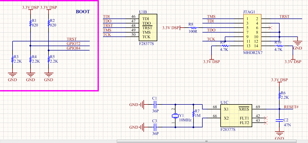
I'm working on tmsf28377s board that I designed it. at first I worked on lunchpad f28377s and I haven't got any problem with it.
after that I designed a board for my projects. But I can't connect to my board.
I use CCS 6.2.
I check all connection jtag connector and voltage power board.
when I connect to board with xds100v2 in test connection show this message :
******************************************************************************************
[Start: Texas Instruments XDS100v2 USB Debug Probe_0]
Execute the command:
%ccs_base%/common/uscif/dbgjtag -f %boarddatafile% -rv -o -F inform,logfile=yes -S pathlength -S integrity
[Result]
-----[Print the board config pathname(s)]------------------------------------
C:\Users\mehdi\AppData\Local\TEXASI~1\CCS\
ti\1\0\BrdDat\testBoard.dat
-----[Print the reset-command software log-file]-----------------------------
This utility has selected a 100- or 510-class product.
This utility will load the adapter 'jioserdesusb.dll'.
The library build date was 'Jul 27 2016'.
The library build time was '18:31:37'.
The library package version is '6.0.407.3'.
The library component version is '35.35.0.0'.
The controller does not use a programmable FPGA.
The controller has a version number of '4' (0x00000004).
The controller has an insertion length of '0' (0x00000000).
This utility will attempt to reset the controller.
This utility has successfully reset the controller.
-----[Print the reset-command hardware log-file]-----------------------------
The scan-path will be reset by toggling the JTAG TRST signal.
The controller is the FTDI FT2232 with USB interface.
The link from controller to target is direct (without cable).
The software is configured for FTDI FT2232 features.
The controller cannot monitor the value on the EMU[0] pin.
The controller cannot monitor the value on the EMU[1] pin.
The controller cannot control the timing on output pins.
The controller cannot control the timing on input pins.
The scan-path link-delay has been set to exactly '0' (0x0000).
-----[The log-file for the JTAG TCLK output generated from the PLL]----------
There is no hardware for programming the JTAG TCLK frequency.
-----[Measure the source and frequency of the final JTAG TCLKR input]--------
There is no hardware for measuring the JTAG TCLK frequency.
-----[Perform the standard path-length test on the JTAG IR and DR]-----------
This path-length test uses blocks of 64 32-bit words.
The test for the JTAG IR instruction path-length succeeded.
The JTAG IR instruction path-length is 6 bits.
The test for the JTAG DR bypass path-length succeeded.
The JTAG DR bypass path-length is 1 bits.
-----[Perform the Integrity scan-test on the JTAG IR]------------------------
This test will use blocks of 64 32-bit words.
This test will be applied just once.
Do a test using 0xFFFFFFFF.
Scan tests: 1, skipped: 0, failed: 0
Do a test using 0x00000000.
Scan tests: 2, skipped: 0, failed: 0
Do a test using 0xFE03E0E2.
Scan tests: 3, skipped: 0, failed: 0
Do a test using 0x01FC1F1D.
Scan tests: 4, skipped: 0, failed: 0
Do a test using 0x5533CCAA.
Scan tests: 5, skipped: 0, failed: 0
Do a test using 0xAACC3355.
Scan tests: 6, skipped: 0, failed: 0
All of the values were scanned correctly.
The JTAG IR Integrity scan-test has succeeded.
-----[Perform the Integrity scan-test on the JTAG DR]------------------------
This test will use blocks of 64 32-bit words.
This test will be applied just once.
Do a test using 0xFFFFFFFF.
Scan tests: 1, skipped: 0, failed: 0
Do a test using 0x00000000.
Scan tests: 2, skipped: 0, failed: 0
Do a test using 0xFE03E0E2.
Scan tests: 3, skipped: 0, failed: 0
Do a test using 0x01FC1F1D.
Scan tests: 4, skipped: 0, failed: 0
Do a test using 0x5533CCAA.
Scan tests: 5, skipped: 0, failed: 0
Do a test using 0xAACC3355.
Scan tests: 6, skipped: 0, failed: 0
All of the values were scanned correctly.
The JTAG DR Integrity scan-test has succeeded.
[End: Texas Instruments XDS100v2 USB Debug Probe_0]
***************************************************************************
when I go to debug mode show this error :
************************************************
Error connecting to the target:
(Error -1135 @ 0x0)
The debug probe reported an error. Confirm debug probe configuration and connections, reset the debug probe, and retry the operation.
(Emulation package 6.0.407.3)
************************************************
massage after ok --> unable to connect target.
---------------------------------------------------------------------------------------------------
after that, I replace xds100v2 with xds510usb and test again
test connection massage:
***********************************************
[Start: Spectrum Digital XDS510USB Emulator_0]
Execute the command:
%ccs_base%/emulation/drivers/sdjtag.exe -f %boarddatafile% -v -X reset -X scantest
[Result]
** BoardFilePath: C:\Users\mehdi\AppData\Local\TEXASI~1\CCS\ti\1\0\BrdDat\testBoard.dat
** Resetting Emulator
-- Emulator is Reset
** Emulator Scan Test
-- Found JTAG IR Length of 6
-- Found 1 device(s) in the scan chain
[End: Spectrum Digital XDS510USB Emulator_0]
******************************************************
and debug message:
**********************************
Error connecting to the target:
Error 0x80000200/-1135
Fatal Error during: OCS,
Unrecoverable emulation error
************************************
please help me.
schematic of jtag section: