Other Parts Discussed in Thread: CONTROLSUITE
Tool/software: Code Composer Studio
Hello,
Having been able to get HRPWM to work, I am a little bothered as the result I got is not as good as I had expected. The HR Configuration is as follows:
EPwm4Regs.CMPA.half.CMPAHR = (1 << 8);       // initialize HRPWM extension
EALLOW;
EPwm4Regs.HRCNFG.all = 0x0;
EPwm4Regs.HRCNFG.bit.EDGMODE = 2;		 // MEP control on falling edge
EPwm4Regs.HRCNFG.bit.CTLMODE = 0;		//CMPAHR control
EPwm4Regs.HRCNFG.bit.HRLOAD  = 0;		//load on ctr = 0
EDIS;
I embedded the coded in my normal epwm code. And I am updating the CMPA and CMPAHR registers with Adc output through epwm ISR. I converted the Adc output before the CMPA and CMPAHR update by following the steps listed in http://www.ti.com/lit/ug/spru924f/spru924f.pdf. My Tsysclkout is 6.667ns and my MEP is calculated as 44. Below is what I got:
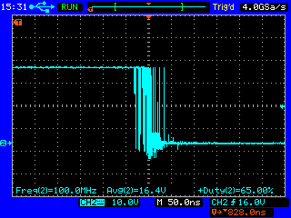
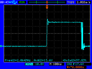
1. With HRPWM

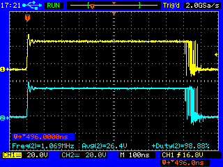
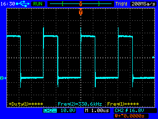
2. NO HRPWM
I really can't tell the difference. Maybe I am doing something wrong.
I'd appreciate advice and pointers.
+ don't mind the frequency displayed (I believe it is as a result of expanding the image, so to speak), the true frequency is 330kHz.
Thanks.
David.