This thread has been locked.

If you have a related question, please click the "Ask a related question" button in the top right corner. The newly created question will be automatically linked to this question.

LAUNCHXL-F28069M: SCI Connection of MCU to Simulink: Always timeouts?

Part Number: LAUNCHXL-F28069M
Other Parts Discussed in Thread: C2000WARE

Hi all! ;)

I am trying to establish serial communication between my computer and my F28069M-LaunchPad via USB cable. My aim is to set certain parameters of a 3-phase inverter (like switching frequency etc.) via SCI blocks on my host computer and send them to the MCU via USB connection. Furthermore, I want to read data from the inverter (like rotor speed, torque, voltages, currents etc.) and to display these values on Simulink scopes on my host computer.
My aim is to achieve a communication like the one shown in this MathWorks tutorial: https://youtu.be/wxYTLbYfBP0?t=2m
For this purpose I created two models:
1.) One model which is built and run on the MCU and contains an "SCI Transmit" block.
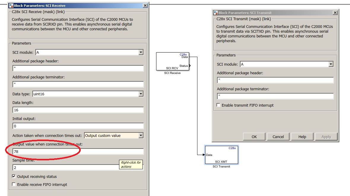
2.) One model that is executed on my host computer after successfully building and beginning to run the other model on the MCU. This model contains an "SCI Setup" block, an "SCI Receive" block and a Simulink scope.
I am using the following settings in both of the models: I chose COM4 as the port for serial communication which is the COM-port of "TI XDS100 Channel B". This port is also shown in the device manager and the bitrate set in the device manager (115200) matches the baudrate I set in the settings of my Simulink models (also 115200).
So I think I took care of all settings to achieve a communication via SCI. But when model 1 is running on the MCU and I start running model 2 on my host computer, the "SCI Receive" block only returns timeouts. I see the default output for timeouts (which I specified in my "SCI Receive" block) on the scope and the timeout is also displayed in the Diagnostic Viewer.
What could be the reason that the host computer only receives timeouts? Have I forgotten some settings? For example, I do not know what "loopback mode" means and I deactivated it. Or do I have to take care about some jumper configurations or positions of the three switches on my LaunchPad?

Best regards,
Armin

  • Hello,
    I am writing to let you know that a C2000 team member has been assigned to this post and should be answering shortly.

    Regards
    Baskaran
  • Hi,

    Please try to run a simple example "c28x_serial_ext"  in external mode and see if the serial connection between host and target is well established.

    For external mode trouble shooting steps follow link as mentioned below:

    e2e.ti.com/.../2090278

    You may also use a tool like PUTTY to read the data as transmitted by target to Host.

    If nothing helps: please contact MathWorks Technical Support for further assistance.

    Regards,

    Venkatesh C

  • Thank you for the help, I will try the models/programs you suggested! ;)
    But maybe you did not understand properly: I tried do send and receive data while NOT using external mode! I flash the program onto the LaunchPad and it starts running. After that, I start the model on the host computer to receive data.
    Or is the SCI connection (also for receiving data from the LaunchPad) only meant to work when the MCU is working in Simulink's external mode? Because when I run the model in external mode and I try to receive data via SCI, I get the same error as mentioned in you link above. But I thought that was normal because I thought those "SCI Transmit" and "SCI Receive" blocks were only meant to work in non-external mode (i.e. normal mode).
  • To test the connections, please build and run the sci echoback examples in C2000Ware.

    The launchpad is able to communicate externally through the mini USB connector.

    sal
  • Hi,

    External mode makes use of the target COM port. If we can get external mode working, then we can rule out issue with COM port.

    It is the same channel that would be used by serial Tx block on target and Serial Rx block on host.

    Regards,

    Venkatesh C

  • Hi all! ;)

    Thank you for the information and help so far! The external mode works with my MCU and Simulink. The "c28x_serial_ext" example and some models created by myself that use external mode ran successfully.
    Afterwards I tried to run the model with the "SCI Transmit" (named "MCU model") using external mode in different configurations. On my computer, the TI XDS100 Channel A refers to COM3 and Channel B refers to COM4. In each configuration I chose one COM port for the external mode in the Simulink configuration and a SCI module for communication in the "SCI Transmit" and "SCI Receive" blocks. The three configurations and their errors are listed below:
    1.) External mode via SCI_A/COM3 and transmitting/receiving data via SCI_B/COM4 - error while building the MCU model
    2.) External mode via SCI_B/COM4 and transmitting/receiving data via SCI_A/COM3 - error while building the MCU model
    3.) External mode via SCI_B/COM4 and transmitting/receiving data via SCI_B/COM4 - MCU model is built successfully, error occurs when host model is started to receive data
    I attached the detailed error messages at the very end of this post. Do you have any idea why these errors occur? Especially the second one which states that module A is used by the external mode although I set external mode to COM4 in the Simulink settings.


    Best regards and thanks in advance,
    Armin


    1.) External mode via SCI_A/COM3 and transmitting/receiving data via SCI_B/COM4 - error while building the MCU model:
    
    Build process completed successfully
    Verbose mode is enabled for External mode. You can disable Verbose in Model Configuration Parameters > Hardware Implementation > Target Hardware Resources > External mode.
    action: EXT_CONNECT
    Error occurred while executing External Mode MEX-file 'ext_serial_win32_comm':
    Failed to connect to the target. A time-out occurred while waiting for the connection response from the target. Possible reasons for the time-out:
    a) The target is not switched on.
    b) The target is not connected to your host machine.
    c) The application for the model is not running on the target. You might have clicked the Stop button. If the Run button is not dimmed, click it. Otherwise, click the Build button, which downloads and runs your application on the target.


    2.) External mode via SCI_B/COM4 and transmitting/receiving data via SCI_A/COM3 - error while building the MCU model:
    
    ### Build procedure for model: 'SCI_Test' aborted due to an error.
    Error evaluating 'InitFcn' callback of C28x SCI Transmit block (mask) 'SCI_Test/SCI Transmit'.
    Caused by:
    The SCI module A is already used by another block or by External Mode.


    3.) External mode via SCI_B/COM4 and transmitting/receiving data via SCI_B/COM4 - MCU model is built successfully, error occurs when host model is started to receive data:
    
    Error evaluating registered method 'Start' of MATLAB S-Function 'c2000hostsci_setup' in 'host_rx/SCI Setup'. The following is the MATLAB call stack (file names and line numbers) that produced this error: 
     ['C:\Program Files\MATLAB\toolbox\matlab\iofun\@serial\fopen.m'] [72]
     ['C:\Program Files\MATLAB\toolbox\target\extensions\processor\shared\ti\blks\masks\c2000hostsci_setup.m'] [156]
    Caused by:
    Open failed: Cannot connect to the COM4 port. Possible reasons are another
    application is connected to the port or the port does not exist.

  • Hi,

    The FTDI chip that is generally used to implement XDS100 reference design come's with 2 ports namely PORTA and PORTB.
    And the TI reference design for XDS100 dedicates the PORTA for JTAG. This leaves the PORTB which can be used for SCI communication.
    Please follow this link and disable the COM port for PORTA which is meant to be used for JTAG.

    processors.wiki.ti.com/.../Using_the_serial_adapter_of_XDS100

    Now we have only one COM port related to PORTB. Which in your case is COM4(SCI_A). The COM port "COM3" that was showing up is because of JTAG PORT of FTDI chip, Please dont mistake it for SCI port of the MCU.
    Now with COM port related to JTAG disabled(follow link above), You will see only one COM port.
    Since external mode default runs on SCI_A, using SCI Tx block which is also working on SCI_A will result in conflict. Hence, when using SCI Tx block on SCI_A don't run external mode, instead use normal mode and download the code to target. Then you should be able to see Rx on Host model.

    Regards,
    Venkatesh C

    If my reply answered your question please click "Verify Answer."
  • Thank you very much, this explanation helped me a lot! :)
    Now I can receive data on the host model when running a program on the MCU in non-external mode.
  • One further question: Should the whole communication between MCU and computer be transmitted via SCI_A? Or is it recommended to use SCI_A for MCU->computer and SCI_B for computer->MCU?

  • You can use the same SCI module for both transmit and receive. I do not see a good reason to isolate these.

    sal
  • I have made this  model to echoback, but it always send 'N' to the serial terminal, which the character I gave for the time out, what can be the problem?

  • Vipin,
    Have you connected the RX to TX on your board?
    For the first time you run your code, there is nothing to get transmitted (because you're not sending any data to TX block) so you don't receive anything too. Since you don't receive anything, the RX block sends out the "78" to TX block (as you set it up in this way). From now on, the TX block sends out 78 to the bus repeatedly and RX block receives 78 continuously.
  • So what should be done to get an echo back, like the same character which we type on the terminal to echo back?
  • If you want to verify the communication, you can go to "Model Configuration Parameters" and select "Enable loopback" which enables the loopback function for self-test and diagnostic purposes:

    If my post answered your question, please click on "Verified answer" button. 

  • Thanks for your reply, will check it