This thread has been locked.

If you have a related question, please click the "Ask a related question" button in the top right corner. The newly created question will be automatically linked to this question.

TMS320F28379D: Could not observe SCL or SDA with an oscilloscope when experimenting the i2c_eeprom example design

Part Number: TMS320F28379D


Hello,

I am supposed to implement I2C communication between TMS320F28379D and a type of FPGA, and I am using F28379D LaunchPad.

At first, I have tested the development kit with a Demo and it worked, so there should be no issue with the hardware or CCS

Second step, I'd like to check if the example i2c_eeprom works with the LaunchPad or not. I have pulled up I2CA pins (GPIO32 and GPIO33) to 3.3V on the board with 4.7K Ohm resistors.

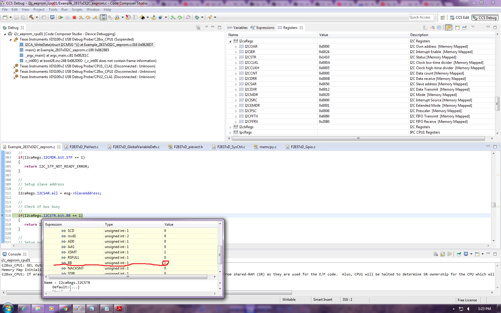
Then I powered the LaunchPad from a computer USB port, built the project (FLASH mode), no error. Under debug mode, when the program is running, I expected to see at least SCL pulses from GPIO33, but except for a constant 3.3V signal, I did not observe anything from oscilloscope. I checked I2CA registers, the values have changed and busbusy is HIGH. A screenshot of the registers are attached here

Stuck here for sometime, please help!

Many thanks in advance!

CY

  • Hello,
    I am writing to let you know that a C2000 team member has been assigned to this post and should be answering shortly.

    Regards
    Baskaran
  • Hi,

    Did you debug and check where the code is getting stuck? There is a possibility that the code is not even reaching till the transmit routine for you to observe the waveform on DSO.

    Regards,
    Gautam
  • Hi Gautam,

    Thanks for your reply. I checked, it stuck at the first time when it run into subroutine I2CA_WriteData, because of I2CSTR.bit.BB = 1. Please look at the attached screenshot

    CY

  • Hello,

    Are you still having trouble with this? What is the state of the SDA pin? You are running the EEPROM example without any edits, correct? What kind of EEPROM are you using?

    Whitney

  • Hi Whitney,

    I still have trouble with this and I didn't change anything with the example code.
    In my case, I2C is to be implemented between this DSP and Lattice FPGA, so I didn't test it with any EEPROM. My FPGA code is ready, and I ever tested the example with my FPGA code without external pull-up, didn't work. When I posted this question, I have disconnected FPGA and added external pull-up, just to make sure the code works at DSP side.

    Looking for ward to your reply.
    Thanks,

    CY
  • By the way, SDA is the same as SCL in the latest experiment - constant 3.3V signal
  • Hi Whitney,

    I left the the debugging for a while, and just picked it up again from yesterday. I have two questions which I want to confirm with you. I would appreciate it much if you could reply me.

    Q1: To get a 7-12MHz I2C module frequency, the I2CPSC register should be set to 19 instead of 6 as shown in the i2c_eeprom example to get 10MHz?
    Q2: Do I have to connect the board with an EEPROM to test the code? Even I don't connect with a slave, I should at least see the address being sent.

    I barely changed anything from the example code except for the frequency setting. Could you take a look and enlighten me what's wrong with my code? Many thanks in advance!

    #include "F28x_Project.h"

    //
    // Defines
    //
    #define I2C_SLAVE_ADDR 0x50 //original value is 0x50*****************************************
    #define I2C_NUMBYTES 2
    #define I2C_EEPROM_HIGH_ADDR 0x00
    #define I2C_EEPROM_LOW_ADDR 0x30

    //
    // Globals
    //
    struct I2CMSG I2cMsgOut1={ I2C_MSGSTAT_SEND_WITHSTOP,
    I2C_SLAVE_ADDR,
    I2C_NUMBYTES,
    I2C_EEPROM_HIGH_ADDR,
    I2C_EEPROM_LOW_ADDR,
    0x12, // Msg Byte 1
    0x34}; // Msg Byte 2

    struct I2CMSG I2cMsgIn1={ I2C_MSGSTAT_SEND_NOSTOP,
    I2C_SLAVE_ADDR,
    I2C_NUMBYTES,
    I2C_EEPROM_HIGH_ADDR,
    I2C_EEPROM_LOW_ADDR};

    struct I2CMSG *CurrentMsgPtr;
    Uint16 PassCount;
    Uint16 FailCount;

    //
    // Function Prototypes
    //
    void I2CA_Init(void);
    Uint16 I2CA_WriteData(struct I2CMSG *msg);
    Uint16 I2CA_ReadData(struct I2CMSG *msg);
    __interrupt void i2c_int1a_isr(void);
    void pass(void);
    void fail(void);

    //
    // Main
    //
    void main(void)
    {
    Uint16 Error;
    Uint16 i;

    CurrentMsgPtr = &I2cMsgOut1;

    //
    // Step 1. Initialize System Control:
    // PLL, WatchDog, enable Peripheral Clocks
    // This example function is found in the F2837xD_SysCtrl.c file.
    //
    InitSysCtrl();

    //
    // Step 2. Initialize GPIO:
    // This example function is found in the F2837xD_Gpio.c file and
    // illustrates how to set the GPIO to it's default state.
    //
    InitGpio();

    //
    // For this example, only init the pins for the SCI-A port.
    // These functions are found in the F2837xD_Gpio.c file.
    GPIO_SetupPinMux(32, GPIO_MUX_CPU1, 1);
    GPIO_SetupPinMux(33, GPIO_MUX_CPU1, 1);
    //
    // Step 3. Clear all __interrupts and initialize PIE vector table:
    // Disable CPU __interrupts
    //
    DINT;

    //
    // Initialize PIE control registers to their default state.
    // The default state is all PIE __interrupts disabled and flags
    // are cleared.
    // This function is found in the F2837xD_PieCtrl.c file.
    //
    InitPieCtrl();

    //
    // Disable CPU __interrupts and clear all CPU __interrupt flags:
    //
    IER = 0x0000;
    IFR = 0x0000;

    //
    // Initialize the PIE vector table with pointers to the shell Interrupt
    // Service Routines (ISR).
    // This will populate the entire table, even if the __interrupt
    // is not used in this example. This is useful for debug purposes.
    // The shell ISR routines are found in F2837xD_DefaultIsr.c.
    // This function is found in F2837xD_PieVect.c.
    //
    InitPieVectTable();

    //
    // Interrupts that are used in this example are re-mapped to
    // ISR functions found within this file.
    //
    EALLOW; // This is needed to write to EALLOW protected registers
    PieVectTable.I2CA_INT = &i2c_int1a_isr;
    EDIS; // This is needed to disable write to EALLOW protected registers

    //
    // Step 4. Initialize the Device Peripherals:
    //
    I2CA_Init();
    DELAY_US(1000000);
    // I2caRegs.I2CSTR.bit.BB = 0;
    //
    // Step 5. User specific code
    //

    //
    // Clear Counters
    //
    PassCount = 0;
    FailCount = 0;

    //
    // Clear incoming message buffer
    //
    for (i = 0; i < I2C_MAX_BUFFER_SIZE; i++)
    {
    I2cMsgIn1.MsgBuffer[i] = 0x0000;
    }

    //
    // Enable __interrupts required for this example
    //

    //
    // Enable I2C __interrupt 1 in the PIE: Group 8 __interrupt 1
    //
    PieCtrlRegs.PIEIER8.bit.INTx1 = 1;

    //
    // Enable CPU INT8 which is connected to PIE group 8
    //
    IER |= M_INT8;
    EINT;

    for(;;)
    {
    //
    // Write data to EEPROM section
    //

    //
    // Check the outgoing message to see if it should be sent.
    // In this example it is initialized to send with a stop bit.
    //
    if(I2cMsgOut1.MsgStatus == I2C_MSGSTAT_SEND_WITHSTOP)
    {
    Error = I2CA_WriteData(&I2cMsgOut1);

    //
    // If communication is correctly initiated, set msg status to busy
    // and update CurrentMsgPtr for the __interrupt service routine.
    // Otherwise, do nothing and try again next loop. Once message is
    // initiated, the I2C __interrupts will handle the rest. Search for
    // ICINTR1A_ISR in the i2c_eeprom_isr.c file.
    //
    if (Error == I2C_SUCCESS)
    {
    CurrentMsgPtr = &I2cMsgOut1;
    I2cMsgOut1.MsgStatus = I2C_MSGSTAT_WRITE_BUSY;
    }
    }

    //
    // Read data from EEPROM section
    //

    //
    // Check outgoing message status. Bypass read section if status is
    // not inactive.
    //
    if (I2cMsgOut1.MsgStatus == I2C_MSGSTAT_INACTIVE)
    {
    //
    // Check incoming message status.
    //
    if(I2cMsgIn1.MsgStatus == I2C_MSGSTAT_SEND_NOSTOP)
    {
    //
    // EEPROM address setup portion
    //
    while(I2CA_ReadData(&I2cMsgIn1) != I2C_SUCCESS)
    {
    //
    // Maybe setup an attempt counter to break an infinite while
    // loop. The EEPROM will send back a NACK while it is performing
    // a write operation. Even though the write communique is
    // complete at this point, the EEPROM could still be busy
    // programming the data. Therefore, multiple attempts are
    // necessary.
    //
    }
    //
    // Update current message pointer and message status
    //
    CurrentMsgPtr = &I2cMsgIn1;
    I2cMsgIn1.MsgStatus = I2C_MSGSTAT_SEND_NOSTOP_BUSY;
    }
    //
    // Once message has progressed past setting up the internal address
    // of the EEPROM, send a restart to read the data bytes from the
    // EEPROM. Complete the communique with a stop bit. MsgStatus is
    // updated in the __interrupt service routine.
    //
    else if(I2cMsgIn1.MsgStatus == I2C_MSGSTAT_RESTART)
    {
    //
    // Read data portion
    //
    while(I2CA_ReadData(&I2cMsgIn1) != I2C_SUCCESS)
    {
    //
    // Maybe setup an attempt counter to break an infinite while
    // loop.
    //
    }
    //
    // Update current message pointer and message status
    //
    CurrentMsgPtr = &I2cMsgIn1;
    I2cMsgIn1.MsgStatus = I2C_MSGSTAT_READ_BUSY;
    }
    }
    }
    }

    //
    // I2CA_Init - Initialize I2CA settings
    //
    void I2CA_Init(void)
    {
    I2caRegs.I2CSAR.all = 0x0050; // Slave address - EEPROM control code, original value is 0050************

    I2caRegs.I2CPSC.all = 19; // Prescaler - need 7-12 Mhz on module clk
    I2caRegs.I2CCLKL = 60; // NOTE: must be non zero, original value is 10***************************
    I2caRegs.I2CCLKH = 30; // NOTE: must be non zero, original value is 5***************************
    I2caRegs.I2CIER.all = 0x24; // Enable SCD & ARDY __interrupts

    I2caRegs.I2CMDR.all = 0x0020; // Take I2C out of reset
    // Stop I2C when suspended

    I2caRegs.I2CFFTX.all = 0x6000; // Enable FIFO mode and TXFIFO
    I2caRegs.I2CFFRX.all = 0x2040; // Enable RXFIFO, clear RXFFINT,

    return;
    }

    //
    // I2CA_WriteData - Transmit I2CA message
    //
    Uint16 I2CA_WriteData(struct I2CMSG *msg)
    {
    Uint16 i;

    //
    // Wait until the STP bit is cleared from any previous master communication.
    // Clearing of this bit by the module is delayed until after the SCD bit is (Is already delayed??)
    // set. If this bit is not checked prior to initiating a new message, the
    // I2C could get confused.
    //
    if(I2caRegs.I2CMDR.bit.STP == 1)
    {
    return I2C_STP_NOT_READY_ERROR;
    }

    //
    // Setup slave address
    //
    I2caRegs.I2CSAR.all = msg->SlaveAddress;

    //
    // Check if bus busy
    //
    if(I2caRegs.I2CSTR.bit.BB == 1)
    {
    return I2C_BUS_BUSY_ERROR;
    }

    //
    // Setup number of bytes to send
    // MsgBuffer + Address
    //
    I2caRegs.I2CCNT = msg->NumOfBytes+2;

    //
    // Setup data to send
    //
    I2caRegs.I2CDXR.all = msg->MemoryHighAddr;
    I2caRegs.I2CDXR.all = msg->MemoryLowAddr;

    for (i=0; i < msg->NumOfBytes; i++)
    {
    I2caRegs.I2CDXR.all = *(msg->MsgBuffer+i);
    }

    //
    // Send start as master transmitter
    //
    I2caRegs.I2CMDR.all = 0x6E20;

    return I2C_SUCCESS;
    }

    //
    // I2CA_ReadData - Read I2CA Message
    //
    Uint16 I2CA_ReadData(struct I2CMSG *msg)
    {
    //
    // Wait until the STP bit is cleared from any previous master communication.
    // Clearing of this bit by the module is delayed until after the SCD bit is
    // set. If this bit is not checked prior to initiating a new message, the
    // I2C could get confused.
    //
    if(I2caRegs.I2CMDR.bit.STP == 1)
    {
    return I2C_STP_NOT_READY_ERROR;
    }

    I2caRegs.I2CSAR.all = msg->SlaveAddress;

    if(msg->MsgStatus == I2C_MSGSTAT_SEND_NOSTOP)
    {
    //
    // Check if bus busy
    //
    if(I2caRegs.I2CSTR.bit.BB == 1)
    {
    return I2C_BUS_BUSY_ERROR;
    }
    I2caRegs.I2CCNT = 2;
    I2caRegs.I2CDXR.all = msg->MemoryHighAddr;
    I2caRegs.I2CDXR.all = msg->MemoryLowAddr;
    I2caRegs.I2CMDR.all = 0x2620; // Send data to setup EEPROM address
    }
    else if(msg->MsgStatus == I2C_MSGSTAT_RESTART)
    {
    I2caRegs.I2CCNT = msg->NumOfBytes; // Setup how many bytes to expect
    I2caRegs.I2CMDR.all = 0x2C20; // Send restart as master receiver
    }

    return I2C_SUCCESS;
    }

    //
    // i2c_int1a_isr - I2CA ISR
    //
    __interrupt void i2c_int1a_isr(void)
    {
    Uint16 IntSource, i;

    //
    // Read __interrupt source
    //
    IntSource = I2caRegs.I2CISRC.all;

    //
    // Interrupt source = stop condition detected
    //
    if(IntSource == I2C_SCD_ISRC)
    {
    //
    // If completed message was writing data, reset msg to inactive state
    //
    if(CurrentMsgPtr->MsgStatus == I2C_MSGSTAT_WRITE_BUSY)
    {
    CurrentMsgPtr->MsgStatus = I2C_MSGSTAT_INACTIVE;
    }
    else
    {
    //
    // If a message receives a NACK during the address setup portion of
    // the EEPROM read, the code further below included in the register
    // access ready __interrupt source code will generate a stop
    // condition. After the stop condition is received (here), set the
    // message status to try again. User may want to limit the number of
    // retries before generating an error.
    if(CurrentMsgPtr->MsgStatus == I2C_MSGSTAT_SEND_NOSTOP_BUSY)
    {
    CurrentMsgPtr->MsgStatus = I2C_MSGSTAT_SEND_NOSTOP;
    }
    //
    // If completed message was reading EEPROM data, reset msg to inactive
    // state and read data from FIFO.
    //
    else if(CurrentMsgPtr->MsgStatus == I2C_MSGSTAT_READ_BUSY)
    {
    CurrentMsgPtr->MsgStatus = I2C_MSGSTAT_INACTIVE;

    for(i=0; i < I2C_NUMBYTES; i++)
    {
    CurrentMsgPtr->MsgBuffer[i] = I2caRegs.I2CDRR.all;
    }
    {
    //
    // Check received data
    //
    for(i=0; i < I2C_NUMBYTES; i++)
    {
    if(I2cMsgIn1.MsgBuffer[i] == I2cMsgOut1.MsgBuffer[i])
    {
    PassCount++;
    }
    else
    {
    FailCount++;
    }
    }
    if(PassCount == I2C_NUMBYTES)
    {
    pass();
    }
    else
    {
    fail();
    }
    }
    }
    }
    }

    //
    // Interrupt source = Register Access Ready
    // This __interrupt is used to determine when the EEPROM address setup
    // portion of the read data communication is complete. Since no stop bit is
    // commanded, this flag tells us when the message has been sent instead of
    // the SCD flag. If a NACK is received, clear the NACK bit and command a
    // stop. Otherwise, move on to the read data portion of the communication.
    //
    else if(IntSource == I2C_ARDY_ISRC)
    {
    if(I2caRegs.I2CSTR.bit.NACK == 1)
    {
    I2caRegs.I2CMDR.bit.STP = 1;
    I2caRegs.I2CSTR.all = I2C_CLR_NACK_BIT;
    }
    else if(CurrentMsgPtr->MsgStatus == I2C_MSGSTAT_SEND_NOSTOP_BUSY)
    {
    CurrentMsgPtr->MsgStatus = I2C_MSGSTAT_RESTART;
    }
    }
    else
    {
    //
    // Generate some error due to invalid __interrupt source
    //
    asm(" ESTOP0");
    }

    //
    // Enable future I2C (PIE Group 8) __interrupts
    //
    PieCtrlRegs.PIEACK.all = PIEACK_GROUP8;
    }

    //
    // pass - Halt debugger and signify pass
    //
    void pass()
    {
    asm(" ESTOP0");
    for(;;);
    }

    //
    // fail - Halt debugger and signify fail
    //
    void fail()
    {
    asm(" ESTOP0");
    for(;;);
    }

    //
    // End of file
    //
  • Hello,

    Q1: You are correct. For a 200MHz system clock value, 19 is the correct prescaler for a 10MHz module clock. The example is wrong.

    Q2: I couldn't get it to work without an EEPROM connected (I didn't even see the address get sent--just SDA and SCL stuck high). I'm not sure why this doesn't work. However, the code worked just fine when I connected the EEPROM though. I ran it with your clocking changes and it was fine.

    Whitney
  • Hi Whitney,

    Thank you so much for the reply. I am very glad I have ordered a couple of I2C eeproms, 24LC256.

    Eventually I should connect a FPGA slave instead of eeprom, do you by any chance could give me any advice?

    Thanks again!

    CY

  • Happy to help! I've never tried doing anything like that, so I don't really have any advice to offer. If you run into trouble during during the integration though, please feel free to reach out to the forum again.

    Whitney