This thread has been locked.

If you have a related question, please click the "Ask a related question" button in the top right corner. The newly created question will be automatically linked to this question.

TMS320F28377S: Spikes on PWM outputs

Expert 2520 points
Part Number: TMS320F28377S
Other Parts Discussed in Thread: TXB0106

Hi

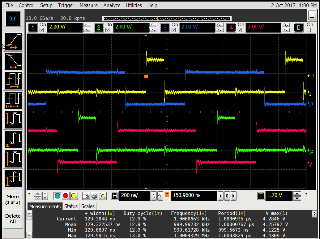
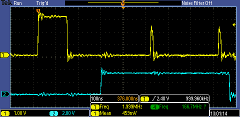
We're going to use 0.5-1MHz 4phase h-bridge, deadband, high resolution involved. Looks like DB generator is heavily broken. In some conditions on some PWM outputs I see strong and fat >2V spikes. See attached oscillogram and compilable code. Standalone Launchpad board, nothing else connected. On oscillogram From top to bottom:

GPIO12 (Launchpad pin 39, PWM7B)

GPIO13 (Launchpad pin 40, PWM7A)

GPIO14 (Launchpad pin 37, PWM8B)

GPIO14 (Launchpad pin 38, PWM8A)

What's wrong with my code? How to fix it reliably?

Thanks

Edward

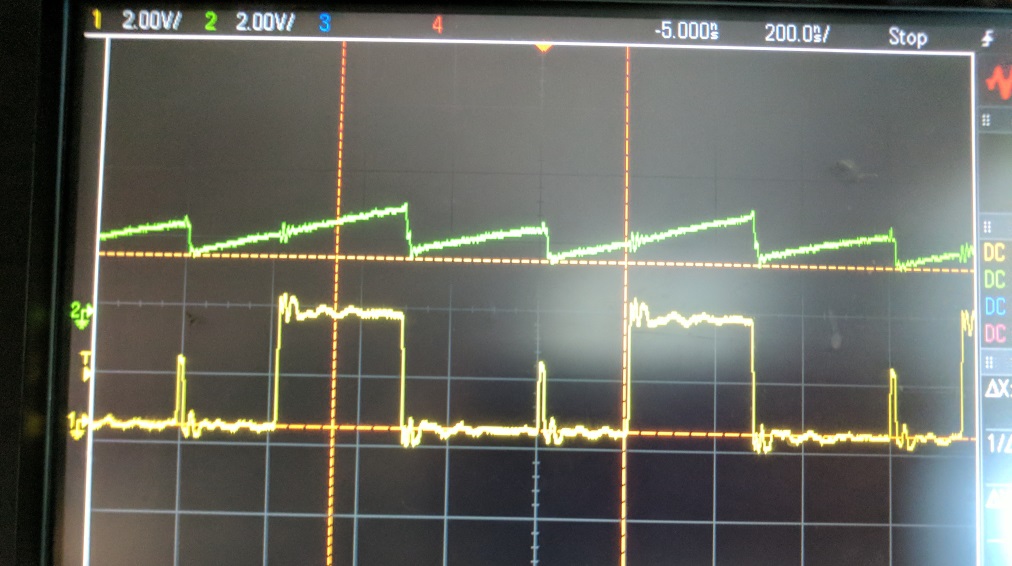
Better grounding but two channels. Spike pulse width is about 10ns:

#include "F28x_Project.h"

#define PHB1REGS EPwm7Regs
#define PHB2REGS EPwm8Regs


#define CPU_SYS_CLOCK   200000ul    // kHz

// assuming default 1/2 divider in PERCLKDIVSEL.EPWMCLKDIV
#define EPWM_CLOCK   (CPU_SYS_CLOCK /2u)  // kHz , 100MHz max

#define PWM_FREQ 1000u   //kHz
#define PWM_MAX (EPWM_CLOCK / PWM_FREQ)

#define ADC_PWM_DIV 2

#define INIPHOFFSET 5


void SetPwmPhb_F(float f)
{
    unsigned int q;
    unsigned long Q;

    f = f * (float)PWM_MAX;
    q = f;

    Q = ((unsigned long)q << 16);


    PHB1REGS.CMPA.all = Q; // linked to PHB2 as well
}


void SetPwmPhbDT(void)
{
    float dt;
    unsigned int q;

    dt = 1500 * 0.02;

    q = dt;

    PHB1REGS.DBRED.bit.DBRED = q;
    PHB2REGS.DBRED.bit.DBRED = q;
    PHB1REGS.DBFED.bit.DBFED = q;
    PHB2REGS.DBFED.bit.DBFED = q;
}

static void InitPWM7(void)
{
    EALLOW;

    GpioCtrlRegs.GPAPUD.bit.GPIO12 = 1;    // Disable pull-up on GPIO12 (EPWM7A)
    GpioCtrlRegs.GPAPUD.bit.GPIO13 = 1;    // Disable pull-up on GPIO13 (EPWM7B)

    GpioCtrlRegs.GPAGMUX1.bit.GPIO12 = 0;   // Configure GPIO2 as EPWM7A
    GpioCtrlRegs.GPAMUX1.bit.GPIO12 = 1;   // Configure GPIO2 as EPWM7A
    GpioCtrlRegs.GPAGMUX1.bit.GPIO13 = 0;   // Configure GPIO3 as EPWM7B
    GpioCtrlRegs.GPAMUX1.bit.GPIO13 = 1;   // Configure GPIO3 as EPWM7B

    EPwm7Regs.TBCTL.bit.CTRMODE = TB_FREEZE; // Count up
    EPwm7Regs.TBCTL.bit.FREE_SOFT = 2; // free run


    EPwm7Regs.TBCTR = 0x0000+INIPHOFFSET;  // initial ctr

    EPwm7Regs.TBPRD = (EPWM_CLOCK / PWM_FREQ)-1;                       // Set timer period
    EPwm7Regs.TBPHS.all = 0x0000;           // Phase is 0


    //
    // Setup TBCLK
    //
    EPwm7Regs.TBCTL.bit.PHSDIR = TB_UP;
    EPwm7Regs.TBCTL.bit.PHSEN = TB_DISABLE;        // Disable phase loading
    EPwm7Regs.TBCTL.bit.SYNCOSEL = TB_SYNC_DISABLE;
    EPwm7Regs.TBCTL.bit.HSPCLKDIV = TB_DIV1;       // Clock ratio to SYSCLKOUT
    EPwm7Regs.TBCTL.bit.CLKDIV = TB_DIV1;          // Slow just to observe on
                                                   // the scope

    EPwm7Regs.CMPCTL.bit.SHDWAMODE = CC_SHADOW;    // Load registers every ZERO
    EPwm7Regs.CMPCTL.bit.SHDWBMODE = CC_SHADOW;
    EPwm7Regs.CMPCTL.bit.LOADAMODE = CC_CTR_ZERO;
    EPwm7Regs.CMPCTL.bit.LOADBMODE = CC_CTR_ZERO;

    //
    // Setup compare
    //
    EPwm7Regs.CMPA.bit.CMPA = 0;

    //
    // Set actions
    //
    EPwm7Regs.AQCTLA.bit.CAU = AQ_CLEAR;
    EPwm7Regs.AQCTLA.bit.ZRO = AQ_SET;
    //EPwm2Regs.AQCTLB.bit.CAU = AQ_SET; // optional
    //EPwm2Regs.AQCTLB.bit.PRD = AQ_CLEAR; // optional

    //
    // Active Low complementary PWMs - setup the deadband
    //
    EPwm7Regs.DBCTL.bit.HALFCYCLE = 1;

    EPwm7Regs.DBCTL.bit.OUT_MODE = DB_FULL_ENABLE;
    EPwm7Regs.DBCTL.bit.POLSEL = DB_ACTV_HIC;
    EPwm7Regs.DBCTL.bit.IN_MODE = DBA_ALL;
    //EPwm2Regs.DBRED.bit.DBRED = 4;
    //EPwm2Regs.DBREDHR.bit.DBREDHR = 100;
    //EPwm2Regs.DBFED.bit.DBFED = 4;
    //EPwm2Regs.DBFEDHR.bit.DBFEDHR = 100;


    // SOCA pulse to ADC
    EPwm7Regs.ETPS.bit.SOCAPRD = ADC_PWM_DIV;
    EPwm7Regs.ETSEL.bit.SOCASEL = ET_CTR_ZERO;     // Select INT on Zero event
    EPwm7Regs.ETSEL.bit.SOCAEN = 1;
    //
    // Interrupt where we will modify the deadband
    //
//    EPwm7Regs.ETSEL.bit.INTSEL = ET_CTR_ZERO;     // Select INT on Zero event
//    EPwm7Regs.ETSEL.bit.INTEN = 1;                // Enable INT
//    EPwm7Regs.ETPS.bit.INTPRD = ET_3RD;           // Generate INT on 3rd event


    EPwm7Regs.HRCNFG.all = 0x0;
    EPwm7Regs.TBCTL.bit.CTRMODE = TB_COUNT_UP; // Count up

    //EPwm7Regs.HRCNFG.bit.AUTOCONV = 1;
    //EPwm7Regs.HRMSTEP.all = 0xFFFF;


    EPwm7Regs.TZSEL.bit.CBC6 = 1;   // on CPU stop
    EPwm7Regs.TZCTL.bit.TZA = TZ_FORCE_LO;
    EPwm7Regs.TZCTL.bit.TZB = TZ_NO_CHANGE;

    EDIS;
}

static void InitPWM8(void)
{
    EALLOW;

    GpioCtrlRegs.GPAPUD.bit.GPIO14 = 1;    // Disable pull-up on GPIO12 (EPWM7A)
    GpioCtrlRegs.GPAPUD.bit.GPIO15 = 1;    // Disable pull-up on GPIO13 (EPWM7B)

    GpioCtrlRegs.GPAGMUX1.bit.GPIO14 = 0;   // Configure GPIO2 as EPWM7A
    GpioCtrlRegs.GPAMUX1.bit.GPIO14 = 1;   // Configure GPIO2 as EPWM7A
    GpioCtrlRegs.GPAGMUX1.bit.GPIO15 = 0;   // Configure GPIO3 as EPWM7B
    GpioCtrlRegs.GPAMUX1.bit.GPIO15 = 1;   // Configure GPIO3 as EPWM7B

    EPwm8Regs.TBCTL.bit.CTRMODE = TB_FREEZE; // Count up
    EPwm8Regs.TBCTL.bit.FREE_SOFT = 2; // free run

    EPwm8Regs.TBCTR = EPWM_CLOCK / PWM_FREQ / 2 -1+INIPHOFFSET;

    EPwm8Regs.TBPRD = (EPWM_CLOCK / PWM_FREQ)-1;                       // Set timer period
    EPwm8Regs.TBPHS.all = 0x0000;           // Phase is 0


    //
    // Setup TBCLK
    //
    EPwm8Regs.TBCTL.bit.PHSDIR = TB_UP;
    EPwm8Regs.TBCTL.bit.PHSEN = TB_DISABLE;        // Disable phase loading
    EPwm8Regs.TBCTL.bit.SYNCOSEL = TB_SYNC_DISABLE;
    EPwm8Regs.TBCTL.bit.HSPCLKDIV = TB_DIV1;       // Clock ratio to SYSCLKOUT
    EPwm8Regs.TBCTL.bit.CLKDIV = TB_DIV1;          // Slow just to observe on
                                                   // the scope

    EPwm8Regs.CMPCTL.bit.SHDWAMODE = CC_SHADOW;    // Load registers every ZERO
    EPwm8Regs.CMPCTL.bit.SHDWBMODE = CC_SHADOW;
    EPwm8Regs.CMPCTL.bit.LOADAMODE = CC_CTR_ZERO;
    EPwm8Regs.CMPCTL.bit.LOADBMODE = CC_CTR_ZERO;

    //
    // Setup compare
    //
    EPwm8Regs.CMPA.bit.CMPA = 0;

    //
    // Set actions
    //
    EPwm8Regs.AQCTLA.bit.CAU = AQ_CLEAR;
    EPwm8Regs.AQCTLA.bit.ZRO = AQ_SET;
    //EPwm2Regs.AQCTLB.bit.CAU = AQ_SET; // optional
    //EPwm2Regs.AQCTLB.bit.PRD = AQ_CLEAR; // optional

    //
    // Active Low complementary PWMs - setup the deadband
    //
    EPwm8Regs.DBCTL.bit.HALFCYCLE = 1;

    EPwm8Regs.DBCTL.bit.OUT_MODE = DB_FULL_ENABLE;
    EPwm8Regs.DBCTL.bit.POLSEL = DB_ACTV_HIC;
    EPwm8Regs.DBCTL.bit.IN_MODE = DBA_ALL;
    //EPwm2Regs.DBRED.bit.DBRED = 4;
    //EPwm2Regs.DBREDHR.bit.DBREDHR = 100;
    //EPwm2Regs.DBFED.bit.DBFED = 4;
    //EPwm2Regs.DBFEDHR.bit.DBFEDHR = 100;

    //
    // Interrupt where we will modify the deadband
    //
//    EPwm7Regs.ETSEL.bit.INTSEL = ET_CTR_ZERO;     // Select INT on Zero event
//    EPwm7Regs.ETSEL.bit.INTEN = 1;                // Enable INT
//    EPwm7Regs.ETPS.bit.INTPRD = ET_3RD;           // Generate INT on 3rd event


    EPwm8Regs.HRCNFG.all = 0x0;

    //EPwm2Regs.HRCNFG.bit.AUTOCONV = 1;
    //EPwm2Regs.HRMSTEP.all = 0xFFFF;

    EPwm8Regs.TBCTL.bit.CTRMODE = TB_COUNT_UP; // Count up

    EPwm8Regs.EPWMXLINK.bit.CMPBLINK = 7-1;
    EPwm8Regs.EPWMXLINK.bit.CMPALINK = 7-1;

    EPwm8Regs.TZSEL.bit.CBC6 = 1;   // on CPU stop
    EPwm8Regs.TZCTL.bit.TZA = TZ_FORCE_LO;
    EPwm8Regs.TZCTL.bit.TZB = TZ_NO_CHANGE;

    EDIS;
}


void main(void)
{
    EALLOW;
    CpuSysRegs.PCLKCR2.all |= (1<< (7-1)) | (1<<(8-1));


    EALLOW;
    CpuSysRegs.PCLKCR0.bit.TBCLKSYNC = 0;


    InitPWM7();
    InitPWM8();

    EALLOW;
    CpuSysRegs.PCLKCR0.bit.TBCLKSYNC = 1;

    SetPwmPhbDT();

    SetPwmPhb_F(0.7211);

    for(;;)
    {
    }
}

  • Hi

    Did I ask something stupid? Is it normal what I observe? Everyone knows ePWM is broken and I just don't see some errata?

    Thanks

    Edward

  • Edward,

    It looks like the spikes are correlated with switching on your other channels.  Try to scope each channel individually to see if the spikes go away.  Only one probe should be connected at a time when you do this.

    If the spikes go away with individual probes, it's just noise coupling between probes on your oscilloscope setup.  If the spikes remain, you should look for sources of cross-talk on your board.

    -Tommy

  • Hi Tommy,

    Nice try with bad scope/probes and channel crosstalk. Oh, if it would be just that.

    See with single probe, zoomed to 20ns/div. It's not really just spike, nice pulse with lowered to about 2V amplitude.

    Few more observations.

    1. "spikes" appear not immediately but some time later. I repeat in CCS debugger CPU Reset-Restart-Resume. Sometimes "spikes" appear (are turned on) sooner, sometimes later from Resume click. From almost immediately to 15 seconds or longer. I wrote these few words and now it is always from 1 or less to 3 seconds. What's that? Is there some undocumented super timer inside? Is it temperature dependent?

    2. Before doing minimal code showing this problem (attached in first message), working with 4 phases I noticed that changing duty cycle at runtime from 0 towards 100%, spikes were turned on at about 70%. Lowering duty cycle down from that point, spikes were disappearing at about 30%. How such hysteresis could be possible? Is there some undocumented timer?

    I see such effects at higher than 500kHz PWM frequencies. Perhaps it can even bite at 500. How could I know I'm safe at 500kHz without years of testing?

    Thank You,

    Regards,

    Edward

  • Edward,

    I see something similar. I'll ask the EPWM experts here for known issues.

    -Tommy
  • Hi Tommy

    Thank you!

    Regards,
    Edward
  • Edward,

    I am still trying to get more information about this, but it looks like the behavior is not present on EPWM8. Are you able to use another PWM instead of EPWM7?

    -Tommy
  • Tommy,

    Behavior is present on other PWM's as well. It depends on many factors, which are hard to understand without good knowledge of what's in DB and other black boxes. Using 4 phases and changing duty cycle, 2V-20ns pulses appear in all channels (7, 8, 2, 6) sooner or later, increasing duty cycle or lowering it.
    It would be even worse if different module instances would work differently. I haven't yet noticed this problem at 500kHz, perhaps 500kHz is safe, but it is very frustrating to have no knowledge about the root of problem.
    Another weird issue I see with initial 4 phases setup at 500kHz. After initialization, 0% duty cycle, low side switches should be set on, and high side switches off. For some weird reason I need to write DBRED and DBFED fields to non zero (I'm using 1), and only then set them to appropriate value. Else low side switches may be kept off until I increase duty cycle quite a lot or change DBFED one more time. I don't see explanation for this in the docs. If there's some very strict and right sequence of initialization, which I'm possibly violating, then where it is in the docs? Ugh.

    Thank You
    Edward
  • Hi Edward,

    If I plop your original code into CCS and run it, I don't see anything other than some minor coupling between ePWMs due to the fast un-loaded edges (see below).

    This includes if I change the duty cycle through the range of possible values. 

    Does that code always give you glitches?

    Note: The below capture is with a call to InitSysCtrl() added to your code.  This didn't seem to make a difference, other than that the CPU is now running at full-speed due the PLL being locked.

    Note: I am not using the launchpad, but instead a TI-internal characterization board.

  • Hi Devin,

    Thank You for trying to reproduce it on characterization board.

    With InitSysCtrl() call it is the same. I'll borrow later another Launchpad from colleague and check if it is the same on it.

    Could you please scan duty cycle with modified code? See attached. I disabled trip zone so PWM continues clicking pause in debugger.

    Scan down:

    Scanning down spikes appear at about 82% and disappear at about 62%.

    Clicking pause in debugger while spikes are on and setting dc variable to 1.0, spikes continue until dc is about 0.83. Then spikes disappear until ~0.82 and appear again at ~0.62 level.

    In other words, once they appear, jumping to 100% duty and clicking run, 100..83% spikes are on, 83..82% off, 82..62% again on.

    Also, if stop CPU while spikes on, and now change dc=0.6, spikes continue from 0.6 to 0.35.

    Scan up:

    Scanning up spikes appear on ePWM7 at about 72% an disappear at about 84% duty cycle.

    Scanning up and clicking pause while spikes are on, then setting dc to anything in 0 .. 0.3 interval, situation is the same like in continuous run: 0..72% spikes are off, 72..84% on, 84..100% off.

    Clicking pause while spikes are on and setting dc to 0.4 spikes are on 40..63%, and then 72..84%.

    Do you have an idea what could cause such behavior? I've nothing connected to Launchpad, just scope and USB cable.

    Launchpad CPU case is markes as follows:

    TMS320

    F28377SPZPT

    YFC-66A496W

    G4

    Regards,

    Edward

    P.S. Something is wrong with forums editor. Clicking on rich text button, it changes line spaces inappropriately. Sorry if not very readable, I don't know how to edit and fix it.

    #include "F28x_Project.h"
    
    #define PHB1REGS EPwm7Regs
    #define PHB2REGS EPwm8Regs
    
    
    #define CPU_SYS_CLOCK   200000ul    // kHz
    
    // assuming default 1/2 divider in PERCLKDIVSEL.EPWMCLKDIV
    #define EPWM_CLOCK   (CPU_SYS_CLOCK /2u)  // kHz , 100MHz max
    
    #define PWM_FREQ 1000u   //kHz
    #define PWM_MAX (EPWM_CLOCK / PWM_FREQ)
    
    #define ADC_PWM_DIV 2
    
    #define INIPHOFFSET 5


    void SetPwmPhb_F(float f)
    {
        unsigned int q;
        unsigned long Q;
    
        f = f * (float)PWM_MAX;
        q = f;
    
        Q = ((unsigned long)q << 16);
    
    
        PHB1REGS.CMPA.all = Q; // linked to PHB2 as well
    }
    
    
    void SetPwmPhbDT(void)
    {
        float dt;
        unsigned int q;
    
        dt = 1500 * 0.02;
    
        q = dt;
    
        PHB1REGS.DBRED.bit.DBRED = q;
        PHB2REGS.DBRED.bit.DBRED = q;
        PHB1REGS.DBFED.bit.DBFED = q;
        PHB2REGS.DBFED.bit.DBFED = q;
    }
    
    static void InitPWM7(void)
    {
        EALLOW;
    
        GpioCtrlRegs.GPAPUD.bit.GPIO12 = 1;    // Disable pull-up on GPIO12 (EPWM7A)
        GpioCtrlRegs.GPAPUD.bit.GPIO13 = 1;    // Disable pull-up on GPIO13 (EPWM7B)
    
        GpioCtrlRegs.GPAGMUX1.bit.GPIO12 = 0;   // Configure GPIO2 as EPWM7A
        GpioCtrlRegs.GPAMUX1.bit.GPIO12 = 1;   // Configure GPIO2 as EPWM7A
        GpioCtrlRegs.GPAGMUX1.bit.GPIO13 = 0;   // Configure GPIO3 as EPWM7B
        GpioCtrlRegs.GPAMUX1.bit.GPIO13 = 1;   // Configure GPIO3 as EPWM7B
    
        EPwm7Regs.TBCTL.bit.CTRMODE = TB_FREEZE; // Count up
        EPwm7Regs.TBCTL.bit.FREE_SOFT = 2; // free run
    
    
        EPwm7Regs.TBCTR = 0x0000+INIPHOFFSET;  // initial ctr
    
        EPwm7Regs.TBPRD = (EPWM_CLOCK / PWM_FREQ)-1;                       // Set timer period
        EPwm7Regs.TBPHS.all = 0x0000;           // Phase is 0


        //
        // Setup TBCLK
        //
        EPwm7Regs.TBCTL.bit.PHSDIR = TB_UP;
        EPwm7Regs.TBCTL.bit.PHSEN = TB_DISABLE;        // Disable phase loading
        EPwm7Regs.TBCTL.bit.SYNCOSEL = TB_SYNC_DISABLE;
        EPwm7Regs.TBCTL.bit.HSPCLKDIV = TB_DIV1;       // Clock ratio to SYSCLKOUT
        EPwm7Regs.TBCTL.bit.CLKDIV = TB_DIV1;          // Slow just to observe on
                                                       // the scope
    
        EPwm7Regs.CMPCTL.bit.SHDWAMODE = CC_SHADOW;    // Load registers every ZERO
        EPwm7Regs.CMPCTL.bit.SHDWBMODE = CC_SHADOW;
        EPwm7Regs.CMPCTL.bit.LOADAMODE = CC_CTR_ZERO;
        EPwm7Regs.CMPCTL.bit.LOADBMODE = CC_CTR_ZERO;
    
        //
        // Setup compare
        //
        EPwm7Regs.CMPA.bit.CMPA = 0;
    
        //
        // Set actions
        //
        EPwm7Regs.AQCTLA.bit.CAU = AQ_CLEAR;
        EPwm7Regs.AQCTLA.bit.ZRO = AQ_SET;
        //EPwm2Regs.AQCTLB.bit.CAU = AQ_SET; // optional
        //EPwm2Regs.AQCTLB.bit.PRD = AQ_CLEAR; // optional
    
        //
        // Active Low complementary PWMs - setup the deadband
        //
        EPwm7Regs.DBCTL.bit.HALFCYCLE = 1;
    
        EPwm7Regs.DBCTL.bit.OUT_MODE = DB_FULL_ENABLE;
        EPwm7Regs.DBCTL.bit.POLSEL = DB_ACTV_HIC;
        EPwm7Regs.DBCTL.bit.IN_MODE = DBA_ALL;
        //EPwm2Regs.DBRED.bit.DBRED = 4;
        //EPwm2Regs.DBREDHR.bit.DBREDHR = 100;
        //EPwm2Regs.DBFED.bit.DBFED = 4;
        //EPwm2Regs.DBFEDHR.bit.DBFEDHR = 100;
    
    
        // SOCA pulse to ADC
        EPwm7Regs.ETPS.bit.SOCAPRD = ADC_PWM_DIV;
        EPwm7Regs.ETSEL.bit.SOCASEL = ET_CTR_ZERO;     // Select INT on Zero event
        EPwm7Regs.ETSEL.bit.SOCAEN = 1;
        //
        // Interrupt where we will modify the deadband
        //
    //    EPwm7Regs.ETSEL.bit.INTSEL = ET_CTR_ZERO;     // Select INT on Zero event
    //    EPwm7Regs.ETSEL.bit.INTEN = 1;                // Enable INT
    //    EPwm7Regs.ETPS.bit.INTPRD = ET_3RD;           // Generate INT on 3rd event
    
    
        EPwm7Regs.HRCNFG.all = 0x0;
        EPwm7Regs.TBCTL.bit.CTRMODE = TB_COUNT_UP; // Count up
    
        //EPwm7Regs.HRCNFG.bit.AUTOCONV = 1;
        //EPwm7Regs.HRMSTEP.all = 0xFFFF;
    
    
        //EPwm7Regs.TZSEL.bit.CBC6 = 1;   // on CPU stop
        //EPwm7Regs.TZCTL.bit.TZA = TZ_FORCE_LO;
        //EPwm7Regs.TZCTL.bit.TZB = TZ_NO_CHANGE;
    
        EDIS;
    }
    
    static void InitPWM8(void)
    {
        EALLOW;
    
        GpioCtrlRegs.GPAPUD.bit.GPIO14 = 1;    // Disable pull-up on GPIO12 (EPWM7A)
        GpioCtrlRegs.GPAPUD.bit.GPIO15 = 1;    // Disable pull-up on GPIO13 (EPWM7B)
    
        GpioCtrlRegs.GPAGMUX1.bit.GPIO14 = 0;   // Configure GPIO2 as EPWM7A
        GpioCtrlRegs.GPAMUX1.bit.GPIO14 = 1;   // Configure GPIO2 as EPWM7A
        GpioCtrlRegs.GPAGMUX1.bit.GPIO15 = 0;   // Configure GPIO3 as EPWM7B
        GpioCtrlRegs.GPAMUX1.bit.GPIO15 = 1;   // Configure GPIO3 as EPWM7B
    
        EPwm8Regs.TBCTL.bit.CTRMODE = TB_FREEZE; // Count up
        EPwm8Regs.TBCTL.bit.FREE_SOFT = 2; // free run
    
        EPwm8Regs.TBCTR = EPWM_CLOCK / PWM_FREQ / 2 -1+INIPHOFFSET;
    
        EPwm8Regs.TBPRD = (EPWM_CLOCK / PWM_FREQ)-1;                       // Set timer period
        EPwm8Regs.TBPHS.all = 0x0000;           // Phase is 0


        //
        // Setup TBCLK
        //
        EPwm8Regs.TBCTL.bit.PHSDIR = TB_UP;
        EPwm8Regs.TBCTL.bit.PHSEN = TB_DISABLE;        // Disable phase loading
        EPwm8Regs.TBCTL.bit.SYNCOSEL = TB_SYNC_DISABLE;
        EPwm8Regs.TBCTL.bit.HSPCLKDIV = TB_DIV1;       // Clock ratio to SYSCLKOUT
        EPwm8Regs.TBCTL.bit.CLKDIV = TB_DIV1;          // Slow just to observe on
                                                       // the scope
    
        EPwm8Regs.CMPCTL.bit.SHDWAMODE = CC_SHADOW;    // Load registers every ZERO
        EPwm8Regs.CMPCTL.bit.SHDWBMODE = CC_SHADOW;
        EPwm8Regs.CMPCTL.bit.LOADAMODE = CC_CTR_ZERO;
        EPwm8Regs.CMPCTL.bit.LOADBMODE = CC_CTR_ZERO;
    
        //
        // Setup compare
        //
        EPwm8Regs.CMPA.bit.CMPA = 0;
    
        //
        // Set actions
        //
        EPwm8Regs.AQCTLA.bit.CAU = AQ_CLEAR;
        EPwm8Regs.AQCTLA.bit.ZRO = AQ_SET;
        //EPwm2Regs.AQCTLB.bit.CAU = AQ_SET; // optional
        //EPwm2Regs.AQCTLB.bit.PRD = AQ_CLEAR; // optional
    
        //
        // Active Low complementary PWMs - setup the deadband
        //
        EPwm8Regs.DBCTL.bit.HALFCYCLE = 1;
    
        EPwm8Regs.DBCTL.bit.OUT_MODE = DB_FULL_ENABLE;
        EPwm8Regs.DBCTL.bit.POLSEL = DB_ACTV_HIC;
        EPwm8Regs.DBCTL.bit.IN_MODE = DBA_ALL;
        //EPwm2Regs.DBRED.bit.DBRED = 4;
        //EPwm2Regs.DBREDHR.bit.DBREDHR = 100;
        //EPwm2Regs.DBFED.bit.DBFED = 4;
        //EPwm2Regs.DBFEDHR.bit.DBFEDHR = 100;
    
        //
        // Interrupt where we will modify the deadband
        //
    //    EPwm7Regs.ETSEL.bit.INTSEL = ET_CTR_ZERO;     // Select INT on Zero event
    //    EPwm7Regs.ETSEL.bit.INTEN = 1;                // Enable INT
    //    EPwm7Regs.ETPS.bit.INTPRD = ET_3RD;           // Generate INT on 3rd event
    
    
        EPwm8Regs.HRCNFG.all = 0x0;
    
        //EPwm2Regs.HRCNFG.bit.AUTOCONV = 1;
        //EPwm2Regs.HRMSTEP.all = 0xFFFF;
    
        EPwm8Regs.TBCTL.bit.CTRMODE = TB_COUNT_UP; // Count up
    
        EPwm8Regs.EPWMXLINK.bit.CMPBLINK = 7-1;
        EPwm8Regs.EPWMXLINK.bit.CMPALINK = 7-1;
    
        //EPwm8Regs.TZSEL.bit.CBC6 = 1;   // on CPU stop
        //EPwm8Regs.TZCTL.bit.TZA = TZ_FORCE_LO;
        //EPwm8Regs.TZCTL.bit.TZB = TZ_NO_CHANGE;
    
        EDIS;
    }


    #define SCANDIR 1 // 0- up, 1 - down
    float dc;
    void main(void)
    {
        InitSysCtrl();
    
        EALLOW;
        CpuSysRegs.PCLKCR2.all |= (1<< (7-1)) | (1<<(8-1));
    
    
        EALLOW;
        CpuSysRegs.PCLKCR0.bit.TBCLKSYNC = 0;
    
    
        InitPWM7();
        InitPWM8();
    
        EALLOW;
        CpuSysRegs.PCLKCR0.bit.TBCLKSYNC = 1;
    
        SetPwmPhbDT();
    
    
        dc = 0.7211;
        SetPwmPhb_F(dc);
    
        for(;;)
        {
            DELAY_US(50000);
    #if SCANDIR
            dc -= 0.001;
            if(dc < 0.0)
                dc += 1.0;
    #else
            dc += 0.001;
            if(dc > 1.0)
                dc -= 1.0;
    #endif
            SetPwmPhb_F(dc);
        }
    }
    

  • Hi

    another Launchpad instance behaves the same.

    Edward
  • Hi Edward.

    Still looks good on my end with new code stepping up or down; no glitches observed.

    I don't have easy access to a single-core launchpad, so I can't try it on that HW immediately, but it seems like the issue is HW related, not with the ePWM IP or SW itself.

    From your first response to Tommy, it seems like the glitch still occurs even if the scope probes on the other channels are disconnected, so this rules out coupling via the scope probes.  What about if you disable the GPIO output (set the mux settings to 0) for all the channels where the glitch is not occurring? If this causes the glitch to disappear, then you know coupling is occurring somewhere on the board. 

    You could also try adding some additional capacitance to the GPIO outputs to make the edges less sharp.   

  • Hi Devin,

    Thanks for trying. But are you using on your board chip from different maskset?

    After removing ePWM8 GPIO initialization (verified no pulses on ePWM8) I still see spikes on ePWM7.
    I even removed whole ePWM8 initialization, powered board on/off to make sure ePWM8 is off. Still spikes on ePWM7.

    Anyway it couldn't be coupling. Coupling couldn't explain why scan up and scan down margins do not match! I still thing there's some timer, which perhaps needs to count to the end, and 1MHz period is perhaps to short. Or something like that. Of course it can't explain 2V amplitude.

    Edward
  • Hi EK,

    The chip I have is the same, but the package is different (I have a 176-pin QFP, while the F2837xS launchpad uses a 100-p QFP).

    We're still working on this.
  • Hi Edward,

    Can you further simplify your EPWM code just for debug? Let's go to the very basics and just use the Time Base Submodule and the Action Qualifier.

    Please let us know the results.

    Regards,

    Kris

  • Hi Kris,

    I need dead band as well. See simplified code, some comments added. Still the same.

    #include "F28x_Project.h"
    
    #define CPU_SYS_CLOCK   200000ul    // kHz
    
    // assuming default 1/2 divider in PERCLKDIVSEL.EPWMCLKDIV
    #define EPWM_CLOCK   (CPU_SYS_CLOCK /2u)  // kHz , 100MHz max
    
    #define PWM_FREQ 1000u   //kHz
    #define PWM_MAX (EPWM_CLOCK / PWM_FREQ)  // PWM period, ePWM clock ticks


    // Set duty cycle, argument as ratio ontime/period
    void SetPwmPhb_F(float f)
    {
        unsigned int q;
        unsigned long Q;
    
        f = f * (float)PWM_MAX;
        q = f;
    
        Q = ((unsigned long)q << 16);
    
    
        EPwm7Regs.CMPA.all = Q; // linked to PHB2 as well
    }
    
    
    // Set DB RED and FED to 150ns, hardcoded constant 1500.
    // 150ns not practical, in real life it will be tune
    void SetPwmPhbDT(void)
    {
        float dt;
        unsigned int q;
    
        dt = 1500 * 0.02;
    
        q = dt;
    
        EPwm7Regs.DBRED.bit.DBRED = q;
        EPwm7Regs.DBFED.bit.DBFED = q;
    }
    
    static void InitPWM7(void)
    {
        EALLOW;
    
        GpioCtrlRegs.GPAPUD.bit.GPIO12 = 1;    // Disable pull-up on GPIO12 (EPWM7A)
        GpioCtrlRegs.GPAPUD.bit.GPIO13 = 1;    // Disable pull-up on GPIO13 (EPWM7B)
    
        GpioCtrlRegs.GPAGMUX1.bit.GPIO12 = 0;   // Configure GPIO2 as EPWM7A
        GpioCtrlRegs.GPAMUX1.bit.GPIO12 = 1;   // Configure GPIO2 as EPWM7A
        GpioCtrlRegs.GPAGMUX1.bit.GPIO13 = 0;   // Configure GPIO3 as EPWM7B
        GpioCtrlRegs.GPAMUX1.bit.GPIO13 = 1;   // Configure GPIO3 as EPWM7B
    
        EPwm7Regs.TBCTL.bit.CTRMODE = TB_FREEZE; // Count up
    
        EPwm7Regs.TBPRD = (EPWM_CLOCK / PWM_FREQ)-1;                       // Set timer period
    
    
        //
        // Setup TBCLK
        //
        EPwm7Regs.TBCTL.bit.PHSDIR = TB_UP;
        EPwm7Regs.TBCTL.bit.PHSEN = TB_DISABLE;        // Disable phase loading
        EPwm7Regs.TBCTL.bit.SYNCOSEL = TB_SYNC_DISABLE;
        EPwm7Regs.TBCTL.bit.HSPCLKDIV = TB_DIV1;       // Clock ratio to SYSCLKOUT
        EPwm7Regs.TBCTL.bit.CLKDIV = TB_DIV1;          // Slow just to observe on
                                                       // the scope
    
        //
        // Set actions
        //
        EPwm7Regs.AQCTLA.bit.CAU = AQ_CLEAR;
        EPwm7Regs.AQCTLA.bit.ZRO = AQ_SET;
    
        //
        // Setup dead band, Active Low complementary
        //
        EPwm7Regs.DBCTL.bit.HALFCYCLE = 1;
    
        EPwm7Regs.DBCTL.bit.OUT_MODE = DB_FULL_ENABLE;
        EPwm7Regs.DBCTL.bit.POLSEL = DB_ACTV_HIC;
        EPwm7Regs.DBCTL.bit.IN_MODE = DBA_ALL;
    
    
        EPwm7Regs.TBCTL.bit.CTRMODE = TB_COUNT_UP; // Count up
    
        EDIS;
    }
    
    
    #define SCANDIR 1 // 0- up, 1 - down
    float dc;          // duty cycle
    
    void main(void)
    {
        InitSysCtrl();
    
        EALLOW;
        CpuSysRegs.PCLKCR2.all |= (1<< (7-1)); // enable ePWM7 clock
    
    
        InitPWM7();
    
        SetPwmPhbDT();
    
        dc = 0.7211;
        SetPwmPhb_F(dc); // set duty
    
        for(;;)
        {
    #if 0      // set to one to scan over duty cycle
            DELAY_US(50000);
    #if SCANDIR
            dc -= 0.001;
            if(dc < 0.0)
                dc += 1.0;
    #else
            dc += 0.001;
            if(dc > 1.0)
                dc -= 1.0;
    #endif
            SetPwmPhb_F(dc);
    #endif
        }
    }
    

    I've noticed something new. With code attached (trip zones by default disabled, FREE_SOFT defaults to stop on next timer increment), sometimes when I click pause button in debugger, I see high side pin (blue) low and low side pin (yellow) high. And sometimes, more often, because duty cycle >50%, high side pin is high and low side pin keeps pulsing with ~2V amplitude and ~3.4MHz frequency. See below:

    run:

    normal OFF state:

    abnormal ON state:

    Regards,

    Edward

  • Edward,

    Thanks for the additional information. Just verifying - are you able to turn off the deadband for debug purposes or the system you're connected to requires it so it cannot be turned off?

    What frequency is your EPWMCLK (the clock going into the EPWM module, not the TBCLK itself)? It looks like you have it defined to be 100 MHz, just verifying that it is what it actually is with your clocking setup.

    10 ns correlates to 1 EPWMCLK cycle if you're running at 100 MHz. Can you scale the TBCLK down further to see if the pulse width changes?


    Regards,
    Kris

  • Kris,

    I need 4 phases, all four complimentary PWM outputs with HRPWM and dead band. In 100pin package on the Launchpad only four ePWM's with HWPWM are bonded out, so I have no other choice, but ePWM2, ePWM6, ePWM7 and ePWM8. First time I noticed spurious pulse operating 4 channels. It was not trivial to reproduce this oddity, I had to move duty cycle up, then down, tune some ePWM registers to see it again. Then I tried to reduce code to the minimum, I removed HRPWM, two ePWM's. I think that code in my first message needed to have ePWM8 enabled to see spikes on ePWM7. But now it is enough to enable just ePWM7. Like I stated previously, I saw spurious pulses at least on 3 ePWMs when operating in 4 phases mode.

    Like you may see in my code, DB unit is set up to produce complimentary output. If I disable DB, of course I don't see spurious pulses. But how knows, perhaps they would come again enabling HRPWM?
    Few minutes ago I was trying in debugger to reset target, run and change DBCTRL.POLSEL from 2 (active high complimentary) to 1 (active low complimentary). Spikes were disappearing, but reducing CMPA to less than ~50% duty, spikes were appearing again.
    Now it changed. I click in debugger at DBCTRL.POLSEL, it shows not 10, which my code sets, but 00. If I click to different DBCTL field (debugger probably rereads DBCTRL), then I see continuous ~3.4MHz sequence of only spurious pulses like in 3rd oscillogram of my previous post. What's that? Do you think I should keep wasting my time observing such oddities?

    Yes, EPWMCLK is 100MHz. Changing TBCTL.CLKDIV and HSPCLKDIV from debugger changes PWM duty and period but doesn't change the form of spurious pulses.
    I also tried to change from debugger ClkCfgRegs.PERCLKDIVSEL.EPWMCLKDIV from default 1 to 0, which means out of specs EPWMCLK frequency, but form of spurious pulses didn't change as well, only period and duration of normal pulse ..........

    Regards,
    Edward
  • Hi Edward,

    I was able to get a launchpad from someone in my building and try the code. I was not able to reproduce the issue with the code as is even with sweeping the duty cycle.

    However, I noticed that the frequency I am seeing is different from the images you posted. Your EPWM period appears to be 1000 ns. When I load the code and run it I am seeing my EPWM period is 2000 ns. If I change the EPWMCLKDIV to be SYSCLK/1 and run the EPWM at 200 MHz (illegal value), then my EPWM is 1000 ns, and afterwards I also see the spikes on the output.

    Can you double check that your EPWMCLKDIV is set to SYSCLK / 2 (EPWMCLKDIV = 1)? It seems like this is most likely the issue. Make sure it is set to that prior to enabling the clocking to your EPWM. If that is correct, then let's double check your system clock frequency and verify it is what you expect by bringing out XCLKOUT on the Launchpad Pin 12.

    Regards,
    Kris

  • Hi Edward,

    The good news is I have reproduced the issue. It seems to be a bug in the board design related to high frequency signals on GPIO13. I reproduced the issue with the EPWM when I changed the TBPRD and CMPA values to your values / 2 to match the PWM frequency and duty cycle.

    To prove this is not the EPWM, I have toggled a GPIO at high frequencies and reproduced the issue. Here is my main() while loop:

    while(1)
    {
    if(GpioDataRegs.GPADAT.bit.GPIO13)
    {
    GpioDataRegs.GPATOGGLE.bit.GPIO13 = 1;
    asm(" RPT #30 || NOP");
    }else
    {
    GpioDataRegs.GPATOGGLE.bit.GPIO13 = 1;
    asm(" RPT #10 || NOP");
    }

    }

    I'm further investigating what is causing the issue on the board. I can run this same code on another board and not see any issues.

    Regards,
    Kris
  • Edward,

    We have identified the problem on the board. The problem is a result of device U2 part txb0106. This bidrectional level shifter has its outputs always enabled and is causing the disruption on the GPIO13.  Please see the snippets I took from the launchpad schematic and the txb0106 datasheet below.

    Here is the waveform of EQEP1I and GPIO13 when the issue is being reproduced (sorry for the phone scope picture, there never seems to be a USB drive when you need one):

    You can see the spurious spikes on GPIO13 correlate with the drop of the EQEP1I signal. As a temporary test, we were able to use a jumper wire to connect EQEP1I to ground and the spikes on GPIO13 were resolved. We do not recommend doing this permanently. If you do not need the level shifter, you could remove R2 (circled in yellow on my diagram) and tie the output enable (OE) of the bidrectional level shifter to GND. This will place the pins in Hi-Z and should prevent the issue.

    Regards,

    Kris

  • Hi Kris,

    Regarding PWM frequency. Yes, I verified ClkCfgRegs.PERCLKDIVSEL.EPWMCLKDIV is 1. Perhaps it was different after running some different code. Clicking CPU Reset button in debugger reverts EPWMCLKDIV to 01 as it should be on power on reset.

    Well, thank you for pointing to U2 buffer. My bad, I thought it was for outputting to the output connector and didn’t read about TXB0106 features. I guess RC at 5V side is what makes it bad. Yes, I saw spurious pulses on GPIO10, GPIO11 and GPIO13, all 3 are used for 4 phase PWM on my prototype board.

    Thank you very much, I’ll remove R2.

    Regards,
    Edward