This thread has been locked.

If you have a related question, please click the "Ask a related question" button in the top right corner. The newly created question will be automatically linked to this question.

Compiler/TMDSLCDK6748: mcasp samples not correlated with CCS graph

Part Number: TMDSLCDK6748
Other Parts Discussed in Thread: TLV320AIC3106,

Tool/software: TI C/C++ Compiler

Hi all,

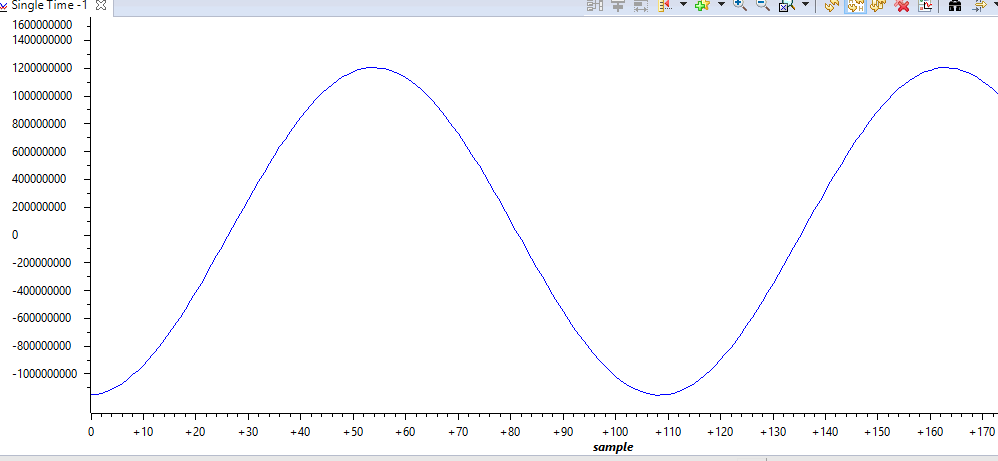
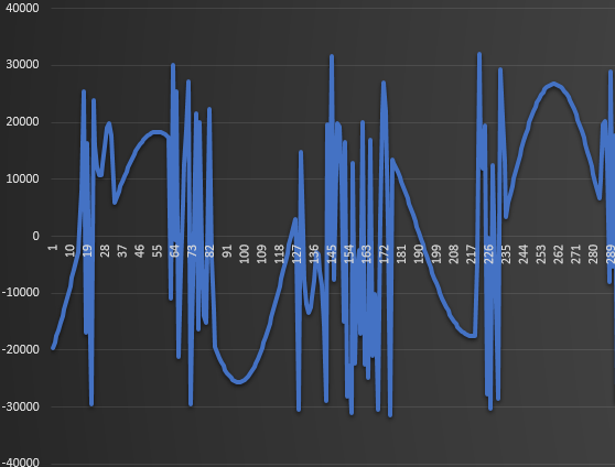
I'm using the 6748 board to capture a single-tone audio input. I'm converting every 2-byte char data to 16-bit signed int.  When I graph the frame in CCS, it looks great:

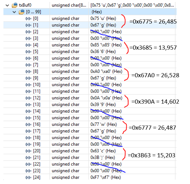
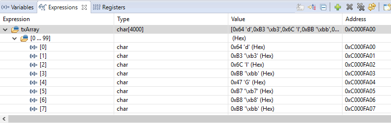
Here's the data that I'm graphing:

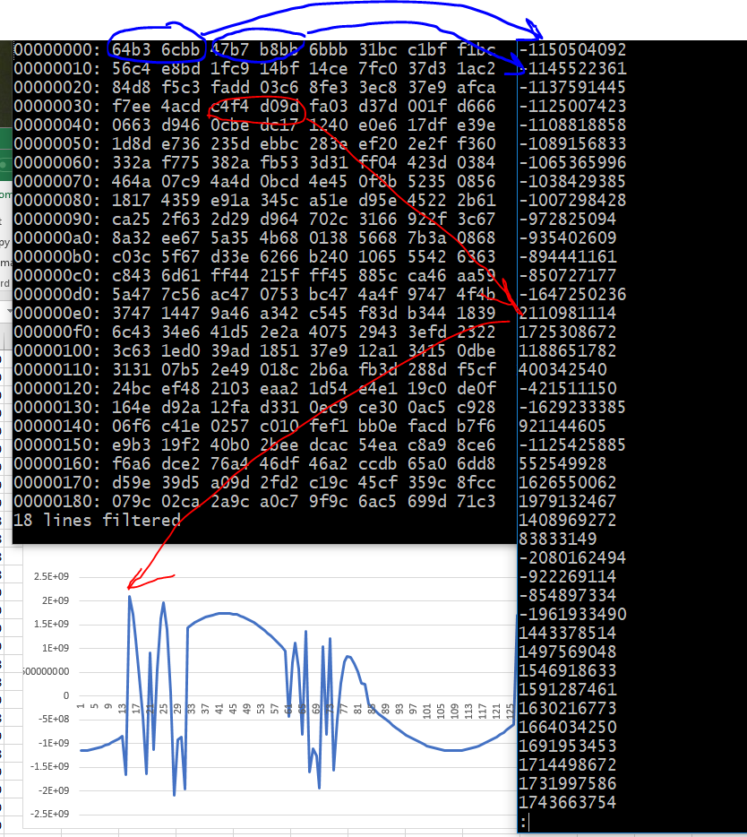
My problem is that when I send the txArray to my computer over UART, I cannot reproduce the graph. In Excel spreadsheet, it looks like this:

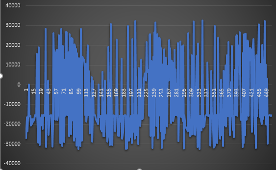
I've tried re-ordering the bytes (little/big-endian) but neither way seems to work.

Any suggestions?

thank you,

Scott

  • Hi Scott,

    I've notified the sw team. Their feedback will be posted here.

    Best Regards,
    Yordan
  • Scott,

    This was sent to us in the Code Composer team. I am not sure what I can do to help. Do you have a way to check if the data that is being sent over UART is correct?

    Are you looking for more info on what the CCS graph does to the values?

    Regards,
    John
  • Hi John,

    I think what I'm is how does the architecture organize the data coming from the codec? For example, I'm interpreting each 2-byte segment as a 16-bit signed integer (and ignoring every other 2-byte data set). Is this correct?

    For example, shown below is the raw data from the txBuf. The first byte is 0x75 and the second 0x67. Using little-endian, I'm converting this to signed integer value 26,485 decimal. Then ignoring the next 2 bytes (both zero). And so on.

    The problem is, if I do this I get noisy waveform, so apparently I'm interpreting the data incorrectly. It looks like it's doing some other kind of channel interleaving, but I don't know what it's doing.

    I hope that makes sense.

    thank you,

    Scott

  • I think this is more of an architecture question, so I'm not sure why it got sent to CCS. Although I would like to know what graph does with the values. That might give me a clue to solving the problem.
    thank you,
    Scott
  • Hi,
    Please let me know if you have any info on how the codec/mcasp encodes the data.
    thank you,
    Scott
  • Hi Scott,

    I can answer the question from the graph side, will take a look if that is the expected behavior or explain it. I'll need some time today/early tomorrow to go through the thread and the specific use case and will respond.  Think how the Codec encodes would be for someone else to answer

    Regards

    Ralph

  • Hi Scott,

    after going through this.....

    Looking at the plot from CCS Graphs screenshot, I doubt that it is a 2 byte data sample. The values are much larger than the +- 32K and more in the range of the +- 2M. So it is plotting 32 bit signed. Also looking at the 1st part of the array and punching the 4 bytes into a calculator I get a value of -1150504092 which look like the 1st value in the plot. 

    So don't think you can just drop byte offset +2 and offset +3

    Regards

    Ralph

  • Hi Ralph,

    Thank you so much for looking at this. I like your idea so I tried it on my data. But I'm still seeing "noise" coming thru my data. You can see a jump at data point 14 where it jumps from a negative value to positive. Shown in red below:

    Do you know if the graphing utility in CCS uses raw data or does it preprocess the data?thank you,

    Scott

  • Scott,

    One detail that may help understand how the data is formatted on the board is to send a screenshot of the Graph Properties. In this case, we can see which parameters are necessary to properly display the data - things such as Q value, data length, etc.

    Regarding the UART communications issue, given that I see parts of a sinewave in the resulting Excel graph, I can't help but wonder if the data is somehow being corrupted during transmission - either by a missing bit here and there, or by a complete corruption. Perhaps if you enable parity on the serial parameters (usually 1, 1.5 or 2 bits) you may at least detect when data was corrupt by the transmission media.

    Otherwise, as you mentioned it may well be a system-level problem that would be better addressed by the experts in the device forum.

    Regards,
    Rafael
  • There's no problem with the UART comms, I verified the data.

    This is an architecture question (although understanding the graph helps). Specifically, how is the data encoded between the codec and the DSP? Is there anyone on the forum who knows anything about the LCD6748 kit on the TI forum?

    Or do you know if there's a similar kit used for audio processing that might have better support?

    thank you,

    Scott

  • I think I see the problem now. When I posted this to the forum, I selected the tool (CCS) that was associated with the issue. But I think I should not have selected that because it seems to vaguely mean "this post will be directed to the CCS team", not "this post will be directed to the hardware team who also happens to know how it interfaces with CCS". So I've started a new post, this time leaving the software unselected.
  • I'm thinking the data are originally encoded as 32-bit floats (which I originallly thougth when I started working on this a month ago), not 32-bit signed ints. I'll have to run some tests to try to reverse engineer it to see which one seems to fit the data.

  • One more question: is there a way to write a variable (ie, an array) to a file from CCS?
  • Scott,

    >>I think I see the problem now. When I posted this to the forum, I selected the tool (CCS) that was associated with the issue. But I think I should not have selected that because it seems to vaguely mean "this post will be directed to the CCS team", not "this post will be directed to the hardware team who also happens to know how it interfaces with CCS". So I've started a new post, this time leaving the software unselected.
    You are correct; the experts on the LCDK are usually at the Device forum. In order to keep the two threads tied, would you mind copying the link to your other thread here? This way people may find the ongoing discussion more easily.

    >>I'm thinking the data are originally encoded as 32-bit floats (which I originally thought when I started working on this a month ago), not 32-bit signed ints. I'll have to run some tests to try to reverse engineer it to see which one seems to fit the data.

    That is why the parameters that you used to plot the sinewave on CCS are important: they will show how the data is encoded.

    Also, since the TMDSLCDK6748 schematics are public, it can be seen the CODEC used TLV320AIC3106 can output data through its serial stream in a number of datapath lengths, which will ultimately govern the way the data is stored and processed by the DSP. Therefore you are right: either someone on the device forum tells you how the CODEC is configured by default or you reverse engineer to see how it is configured.

    >>One more question: is there a way to write a variable (ie, an array) to a file from CCS?
    Yes. You can do this in at least two ways:
    - Manually from the Memory Browser viewer. Check section 3.3 of the reference below for details.
    - Automatically by properly setting a breakpoint at the end of the process that fills the data input buffer. Check section 3.4 on how to access breakpoint features and you can see there is an option to write data to a file.

    processors.wiki.ti.com/.../GSG:Debugging_projects_v5

    Hope this helps,
    Rafael
  • Yes, this helps. Looking at the graph I see it's interpreting the samples as 32-bit signed. So now it looks like I may have a data corruption in the uart.
    thank you,
    Scott
  • Once I figured out it's 32-bit and I'm able to save a memory footprint I can fix the problem.