This thread has been locked.

If you have a related question, please click the "Ask a related question" button in the top right corner. The newly created question will be automatically linked to this question.

JTAG XDS100+RS232 V1.0 drivers issue on C2000 Digital Power Training Kit TMDSC2KWRKSHPKIT

On board jtag was working till yesterday but today it is giving some errors. 

I have tried some solution from e2e post's related to the errors(mentioned below)

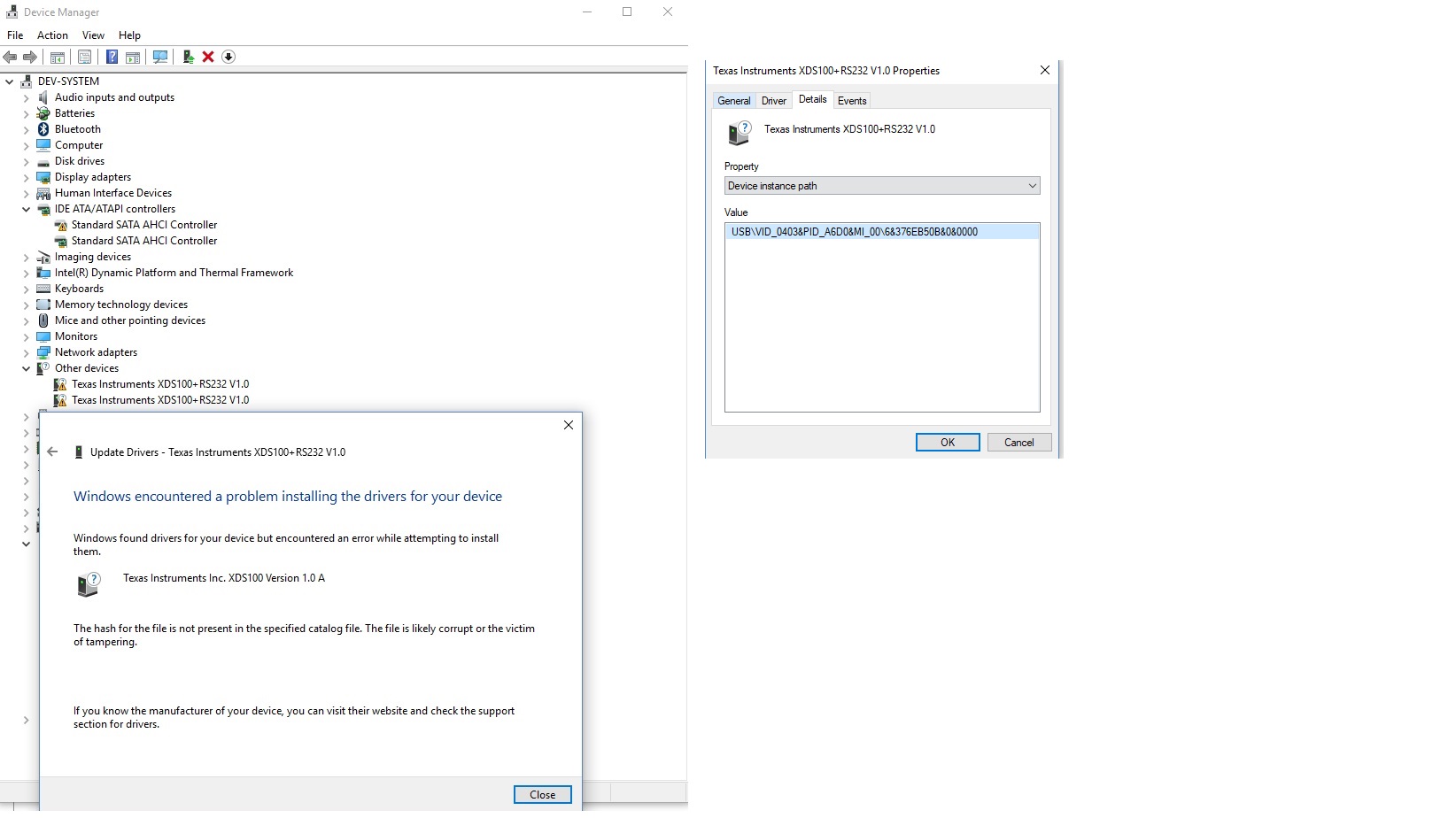
1.)  JTAG XDS100+RS232 V1.0  drivers issue

2.)   Error in JTAG Connection Test:- The value is '-151' (0xffffff69). The title is 'SC_ERR_FTDI_OPEN'.

Solution Tried:

1.) reinstalled the ccs V7.2(no luck)

2.)  tried to update drivers from control suit xds100 driver location using device manager(no luck)

3.) Tried on another laptop with fresh ccs installation(no luck)

4.) Tried related suggestion from  

JTAG Test Connection Log:

[Start: Texas Instruments XDS100v1 USB Debug Probe_0]


Execute the command:


%ccs_base%/common/uscif/dbgjtag -f %boarddatafile% -rv -o -F inform,logfile=yes -S pathlength -S integrity


[Result]


-----[Print the board config pathname(s)]------------------------------------


C:\Users\Parveen\AppData\Local\TEXASI~1\

    CCS\ti\0\0\BrdDat\testBoard.dat


-----[Print the reset-command software log-file]-----------------------------


This utility has selected a 100- or 510-class product.

This utility will load the adapter 'jioserdesusb.dll'.


An error occurred while soft opening the controller.


-----[An error has occurred and this utility has aborted]--------------------


This error is generated by TI's USCIF driver or utilities.


The value is '-151' (0xffffff69).

The title is 'SC_ERR_FTDI_OPEN'.


The explanation is:

One of the FTDI driver functions used during the connect

returned bad status or an error. The cause may be one or

more of: no XDS100 is plugged in, invalid XDS100 serial number,

blank XDS100 EEPROM, missing FTDI drivers, faulty USB cable.

Use the xds100serial command-line utility in the 'common/uscif'

folder to verify the XDS100 can be located.


[End: Texas Instruments XDS100v1 USB Debug Probe_0]

Need help to make it work.

thanks

Pushpender

  • Hello Christopher

    Yes i have reviewed this link but still problem is not solved.

    Followed the steps from link didn't worked.

    I have tried fresh installation of   ccs v7 on another pc bt still the xds100 is detected in dual RS232 mode and followed the steps in post but still it is showing Dual XDS100+RS232 V1.0 in device manager.

    after disabling digital signature check for drivers i am able to install the drivers but still jtag connection test failed.

    log details are below:

    [Start: Texas Instruments XDS100v1 USB Debug Probe_0]

    Execute the command:

    %ccs_base%/common/uscif/dbgjtag -f %boarddatafile% -rv -o -F inform,logfile=yes -S pathlength -S integrity

    [Result]

    -----[Print the board config pathname(s)]------------------------------------

    C:\Users\Parveen\AppData\Local\TEXASI~1\

       CCS\ti\0\0\BrdDat\testBoard.dat

    -----[Print the reset-command software log-file]-----------------------------

    This utility has selected a 100- or 510-class product.

    This utility will load the adapter 'jioserdesusb.dll'.

    The library build date was 'May 23 2017'.

    The library build time was '19:37:36'.

    The library package version is '6.0.628.3'.

    The library component version is '35.35.0.0'.

    The controller does not use a programmable FPGA.

    The controller has a version number of '4' (0x00000004).

    The controller has an insertion length of '0' (0x00000000).

    This utility will attempt to reset the controller.

    This utility has successfully reset the controller.

    -----[Print the reset-command hardware log-file]-----------------------------

    The scan-path will be reset by toggling the JTAG TRST signal.

    The controller is the FTDI FT2232 with USB interface.

    The link from controller to target is direct (without cable).

    The software is configured for FTDI FT2232 features.

    The controller cannot monitor the value on the EMU[0] pin.

    The controller cannot monitor the value on the EMU[1] pin.

    The controller cannot control the timing on output pins.

    The controller cannot control the timing on input pins.

    The scan-path link-delay has been set to exactly '0' (0x0000).

    -----[The log-file for the JTAG TCLK output generated from the PLL]----------

    There is no hardware for programming the JTAG TCLK frequency.

    -----[Measure the source and frequency of the final JTAG TCLKR input]--------

    There is no hardware for measuring the JTAG TCLK frequency.

    -----[Perform the standard path-length test on the JTAG IR and DR]-----------

    This path-length test uses blocks of 64 32-bit words.

    The test for the JTAG IR instruction path-length failed.

    The JTAG IR instruction scan-path is stuck-at-ones.

    The test for the JTAG DR bypass path-length failed.

    The JTAG DR bypass scan-path is stuck-at-ones.

    -----[Perform the Integrity scan-test on the JTAG IR]------------------------

    This test will use blocks of 64 32-bit words.

    This test will be applied just once.

    Do a test using 0xFFFFFFFF.

    Scan tests: 1, skipped: 0, failed: 0

    Do a test using 0x00000000.

    Test 2 Word 0: scanned out 0x00000000 and scanned in 0xFFFFFFFF.

    Test 2 Word 1: scanned out 0x00000000 and scanned in 0xFFFFFFFF.

    Test 2 Word 2: scanned out 0x00000000 and scanned in 0xFFFFFFFF.

    Test 2 Word 3: scanned out 0x00000000 and scanned in 0xFFFFFFFF.

    Test 2 Word 4: scanned out 0x00000000 and scanned in 0xFFFFFFFF.

    Test 2 Word 5: scanned out 0x00000000 and scanned in 0xFFFFFFFF.

    Test 2 Word 6: scanned out 0x00000000 and scanned in 0xFFFFFFFF.

    Test 2 Word 7: scanned out 0x00000000 and scanned in 0xFFFFFFFF.

    The details of the first 8 errors have been provided.

    The utility will now report only the count of failed tests.

    Scan tests: 2, skipped: 0, failed: 1

    Do a test using 0xFE03E0E2.

    Scan tests: 3, skipped: 0, failed: 2

    Do a test using 0x01FC1F1D.

    Scan tests: 4, skipped: 0, failed: 3

    Do a test using 0x5533CCAA.

    Scan tests: 5, skipped: 0, failed: 4

    Do a test using 0xAACC3355.

    Scan tests: 6, skipped: 0, failed: 5

    Some of the values were corrupted - 83.3 percent.

    The JTAG IR Integrity scan-test has failed.

    -----[Perform the Integrity scan-test on the JTAG DR]------------------------

    This test will use blocks of 64 32-bit words.

    This test will be applied just once.

    Do a test using 0xFFFFFFFF.

    Scan tests: 1, skipped: 0, failed: 0

    Do a test using 0x00000000.

    Test 2 Word 0: scanned out 0x00000000 and scanned in 0xFFFFFFFF.

    Test 2 Word 1: scanned out 0x00000000 and scanned in 0xFFFFFFFF.

    Test 2 Word 2: scanned out 0x00000000 and scanned in 0xFFFFFFFF.

    Test 2 Word 3: scanned out 0x00000000 and scanned in 0xFFFFFFFF.

    Test 2 Word 4: scanned out 0x00000000 and scanned in 0xFFFFFFFF.

    Test 2 Word 5: scanned out 0x00000000 and scanned in 0xFFFFFFFF.

    Test 2 Word 6: scanned out 0x00000000 and scanned in 0xFFFFFFFF.

    Test 2 Word 7: scanned out 0x00000000 and scanned in 0xFFFFFFFF.

    The details of the first 8 errors have been provided.

    The utility will now report only the count of failed tests.

    Scan tests: 2, skipped: 0, failed: 1

    Do a test using 0xFE03E0E2.

    Scan tests: 3, skipped: 0, failed: 2

    Do a test using 0x01FC1F1D.

    Scan tests: 4, skipped: 0, failed: 3

    Do a test using 0x5533CCAA.

    Scan tests: 5, skipped: 0, failed: 4

    Do a test using 0xAACC3355.

    Scan tests: 6, skipped: 0, failed: 5

    Some of the values were corrupted - 83.3 percent.

    The JTAG DR Integrity scan-test has failed.

    [End: Texas Instruments XDS100v1 USB Debug Probe_0]

    I have F28027 launchpad and with same drivers and ccs it is working fine so i think the problem is not in drivers side.

    Regards

    pushpender

  • Hi Pushpender,

    Can you confirm that Windows Device Manager shows XDS100 entries when the USB cable is plugged in?  I think you have mentioned that you do, but just making sure.

    Is the main board's J1 ([Main]-J1) populated?  It needs to be populated in order for CCS to work with the kit.  It enables the JTAG debug probe's TRSTn to go to the device.
    (you can find the relevant schematics in the zip file located in the following wiki: http://processors.wiki.ti.com/index.php/C2000_DPSWorkshop)

    Hopefully this helps.


    Thank you,
    Brett

  • Hi Brett

    Thanks for the tip, After populating J1 everything is working fine.

    Regards
    Pushpender