This thread has been locked.

If you have a related question, please click the "Ask a related question" button in the top right corner. The newly created question will be automatically linked to this question.

F28M36H33B2: Gui composer USB-UART Monitor connection not workin

Part Number: F28M36H33B2

I am trying to connect my cloud Gui composer app to the target via the USB-UART monitor. I have added the Serial_Cmd_Monitor.h and .c files to my project and added a UART communication in Target configurations on Com 4 where my USB to serial adapter is connected. Then I configure the gui composer app to use USB-uart and try to connect. I have selected Com 4 but it seems want to connect to Com 14 and oviously fails because there is nothing on Com 14. How do I get it to connect to Com 4? I'm really struggling with this, the Monitor based comms tutorial is very high level. Is there a more detailed Tut for USB-UART monitor setup? 
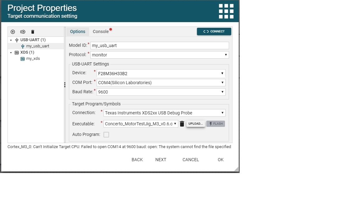
  • Are you sure you are selecting the right COM port? In you picture the description for COM4 shows Silicon Laboratories, this is a string that operating system obtains from USB device. I would check using device manager whether you are talking to the right COM port. Purely based on information in this screen capture the wrong COM port is selected.

    If this is not the issue then I would try to confirm that your firmware with monitor is working correctly. The best way that I found how to do this is through CCS Desktop, where you can simulate how GUI Composer communicates over UART. The link below contains more information on Program model with Uart. The wiki page is for GCv1 , however, starting a debug session where JTAG and COM port connection are active at the same time would be the same. The target firmware and protocol are identical as well. The main difference is the how GUI is constructed. Then you should be able to select UART Connection or JTAG connection in expression view see the same variables updating. UART Connection does not offer full debug capabilities thus you can only read/write memory which means that expression view/memory view should work but not much else.

    processors.wiki.ti.com/.../ProgramModelUart_GuiComposer

    martin
  • I am using a Silicon lab serial - usb converter which is connected to my target, and according to my device manager it is connected to COM4, that is why I selected COM 4. So it should be the correct COM port. 

    Still, if I selected COM4, whether it is the correct one or not, why does it try to connect to COM14?

    Yes I have also tried that example in the wiki you sent but it still does not work. I will follow the steps again and see. 

  • It is probably trying to use COM14 because you have some other Texas Instruments COM device on that COM port. TI Cloud Agent, which is what GUI Composer uses to communicate with the device, tries to automatically guess the right COM port based on selected device, Debug Probe and description information provided by the OS. It looks like it is guessing COM14 in this case. 

    It will try to do this when you are in project properties and when you preview or run the app. I am guessing that you are trying to set it to COM4 through project properties in design mode. However, when you preview the app above mentioned detection logic will be triggered again. Depending on which project template you used you may need to add an "Options" menu that allows you to manually override COM port setting in a running app. From widget palette find Options menu and drag it to "File" or "Edit" menu, then preview an app. This should open a new tab with your application in running mode. You would then need to open that Options menu select the right COM port and click Configure which should disconnect and reconnect using new COM port. 

    If you are doing something different then please let me know which steps you are taking to see the issue.   

    Martin


  • The other Texas Instruments COM devices are on COM6 and 7. According to device manager there is nothing on COM14.

    I added the option menu and preview the app, then select COM4, but it still does not work. Aslo exported to CCS Desktop and tried it from there, does not work.

    I also tried to force the serial to USB converter to be on COM14 by changing it in device manger. Still the Gui composer gives the error:

    TICloudAgent Config Error:  Cortex_M3_0: Can't Initialize Target CPU: Failed to open COM14 at 9600 baud: open: The system cannot find the file specified

    This is what I did to my target application, can you please confirm if this is correct or did I miss someting?

    • 1. I added the 2 Serial_Cmd_Monitor (.c and .h) files to my project. (Files attached)
    • I only changed the Write8bitByteToCOM function to interface with my target UART:

    // override these depends on target
    void Write8bitByteToCOM(unsigned char c)
    {
    UARTCharPut(UART0_BASE, c); //added by Albert
    // uartTxByte(c & 0xff);
    }

    • I configured UART0 on my Target and added the function ClearBufferRelatedParam():

    //--------------------------------------
    // UART0 Setup 
    //--------------------------------------
    // Configure the UART for 115,200, 8-N-1 operation.
    UARTConfigSetExpClk(UART0_BASE, SysCtlClockGet(SYSTEM_CLOCK_SPEED), 9600,
    (UART_CONFIG_WLEN_8 | UART_CONFIG_STOP_ONE |
    UART_CONFIG_PAR_NONE));

    // Enable the UART interrupt.
    IntRegister(INT_UART0, UART0IntHandler);
    IntEnable(INT_UART0);
    UARTIntEnable(UART0_BASE, UART_INT_RX | UART_INT_RT);
    IntPrioritySet(INT_UART0,0x80);

    UARTFIFOEnable(INT_UART0);
    UARTFIFOLevelSet(INT_UART0,UART_FIFO_TX4_8,UART_FIFO_RX1_8);

    //set UART's 485 Line Driver Direction
    GPIOPinWrite(UART0_485_DIR_BASE, UART0_485_DIR_PIN,0); //set to low (Recieve mode)

    ClearBufferRelatedParam();

    • I have an interrupt that reads UART0 and added the receivedDataCommand function in there:

    //*****************************************************************************
    // The UART0 interrupt handler.
    //*****************************************************************************

    void UART0IntHandler(void)
    {
    unsigned long ulStatus;

    // Get the interrupt status.
    ulStatus = UARTIntStatus(UART0_BASE, true);


    while( UARTCharsAvail(UART0_BASE) )
    {
    receivedDataCommand(UARTCharGetNonBlocking(UART0_BASE));
    }

    // Clear the asserted interrupts.
    UARTIntClear(UART0_BASE, ulStatus);
    }

    Serial_Cmd_Monitor.c
    //#include "uart.h"
    #include "Serial_Cmd_Monitor.h"
    
    #define     TEMP_THRESHOLD      4
    
    #define		RW_CMD 			0x80
    
    #define		EXTENSION_BYTE		0x07
    
    
    #define UART0_BASE             0x4000C000   // UART0  //added by AS
    
    
    //RW CMD TYPE
    #define READ 1
    #define WRITE 0
    //ENDIANNESS
    #define BIG_ENDIAN 1
    #define LITTLE_ENDIAN 0
    //ADDRESSIBLE SIZE
    #define ADDRESSIBLE_32_BIT 1
    #define ADDRESSIBLE_16_BIT 0
    // override these depends on target: CMD_BUFFER_SIZE =  5 + sizeOfMauIn8BitByte * 63
    #define CMD_BUFFER_SIZE 68 //1 + 4 + 63 = 68
    
    unsigned char gInCmdBuffer[CMD_BUFFER_SIZE];
    unsigned short gInCmdBufferIdx = 0;
    volatile unsigned short gInCmdSkipCount;
    
    void ClearBufferRelatedParam();
    
    // override these depends on target
    int GetTargetEndianness()
    {
    	return LITTLE_ENDIAN;
    }
    // override these depends on target
    void Write8bitByteToCOM(unsigned char c)
    {
    	UARTCharPut(UART0_BASE, c); //added by AS
    //	uartTxByte(c & 0xff);
    }
    
    int GetSizeOfMAUIn8bitByte()
    {
    	unsigned char maxMAUValue = (unsigned char)(-1);
    	switch (maxMAUValue)
    	{
    	case 0xff:
    		return 1;
    	case 0xffff:
    		return 2;
    	default:
    		return 0;
    	}
    }
    
    int WriteToCmdBuffer(unsigned char* buf, unsigned short* bufIdx, unsigned char d)
    {
    	if ( (*bufIdx) < CMD_BUFFER_SIZE )
    	{
    		buf[*bufIdx] = d & 0xff;
    		(*bufIdx)++;
    		return 0;
    	}
    
    	return 1;
    }
    
    void ResetInCmdBuffer()
    {
    	gInCmdBufferIdx = 0;
    }
    
    int WriteByteToInCmdBuffer(unsigned char d)
    {
    	return WriteToCmdBuffer(gInCmdBuffer, &gInCmdBufferIdx, d);
    }
    
    int GetTransferSizeInMAU() //transfer size refer to the words to read/write of a given cmd, not the number of bytes for the whole cmd packet
    {
    	return (gInCmdBuffer[0] & 0x3f);
    }
    
    int VerifyInputCmdHeaders()
    {
    	return ((gInCmdBuffer[0] & 0x80) == 0x80) ? 0 : 1;
    }
    
    int GetInputCmdType()
    {
    	return (gInCmdBuffer[0] & 0x80);
    }
    
    int GetRWFlag()//equivalent to endianness on the MAU in transmission
    {
    	int ret = ((gInCmdBuffer[0] >> 6) & 0x1); //
    	return ret;
    }
    
    unsigned char* GetInCmdAddress()
    {
    	unsigned char* addr = 0;
    	unsigned long addr_value = 0;
    	int i = 0;
    	int addressSize = 4; // always use 32bit address
    	for (; i < addressSize; i++)
    	{
    		addr_value |= (unsigned long)( gInCmdBuffer[1 + i] << 8 * (addressSize - 1 - i) ); //big endian
    	}
    
    	addr = (unsigned char*) addr_value;
    	return addr;
    }
    
    void WriteMAUToCOM(unsigned char d)
    {
    	int MAUSize = GetSizeOfMAUIn8bitByte();
    
    	switch (MAUSize)
    	{
    	case 1:
    		Write8bitByteToCOM(d);
    		break;
    	case 2:
    	{
    		unsigned char MAU[2];
    		MAU[0] = (unsigned char)(d & 0xff);
    		MAU[1] = (unsigned char)(d >> 8);
    		if (GetTargetEndianness() == LITTLE_ENDIAN)
    		{
    			Write8bitByteToCOM(MAU[0]);
    			Write8bitByteToCOM(MAU[1]);
    		} else {
    			Write8bitByteToCOM(MAU[1]);
    			Write8bitByteToCOM(MAU[0]);
    		}
    	}
    	break;
    	default://only handles 8bit, 16bit MAU
    		break;
    	}
    }
    
    unsigned char GetWriteCmdDataMAU(int idx)
    {
    	unsigned char startIdx = 1 + 4;
    
    	unsigned char val = 0;
    	int MAUSize = GetSizeOfMAUIn8bitByte();
    	int byteOffset = idx*MAUSize;
    
    	switch (MAUSize)
    	{
    	case 1:
    		val = gInCmdBuffer[startIdx + byteOffset];
    		break;
    	case 2:
    		if (GetTargetEndianness() == LITTLE_ENDIAN)
    		{
    			val = ( gInCmdBuffer[startIdx + byteOffset + 1] << 8 ) | gInCmdBuffer[startIdx + byteOffset];
    		} else {
    			val = ( gInCmdBuffer[startIdx + byteOffset] | gInCmdBuffer[startIdx + byteOffset + 1] << 8 );
    		}
    		break;
    	default://only handles 8bit, 16bit MAU
    		break;
    	}
    
    	return val;
    }
    
    void ClearBufferRelatedParam()
    {
    	gInCmdSkipCount = 0;
    	gInCmdBufferIdx	= 0;
    }
    
    void MemAccessCmd(int RW)
    {
    	unsigned short MAUsToRead = 0;
    	unsigned char dataChar = 0;
    	unsigned char* addr = GetInCmdAddress();
    	unsigned short i, j;
    
    	for ( j = 0; j < 1; j++ )
    	{
    		Write8bitByteToCOM(gInCmdBuffer[j]);
    	}
    
    	MAUsToRead = GetTransferSizeInMAU();
    	for ( i = 0; i < MAUsToRead; i++ )
    	{
    		if (RW == READ)
    		{
    			dataChar = *(addr + i);
    			WriteMAUToCOM(dataChar);
    		} else { //WRITE
    			dataChar = GetWriteCmdDataMAU(i);
    			*(addr + i) = dataChar;
    		}
    	}
    }
    
    int ProcessCommand()
    {
    	if ( VerifyInputCmdHeaders() )
    	{
    		return 1;
    	}
    
    	switch ( GetInputCmdType() )
    	{
    	case RW_CMD:
    		MemAccessCmd(GetRWFlag());
    		break;
    	default:
    		return 1;
    	}
    
    	return 0;
    }
    
    void receivedDataCommand(unsigned char d) // only lower byte will be used even if MAU is bigger than 1 byte
    {
    	WriteByteToInCmdBuffer(d);
    
    	if (gInCmdSkipCount > 0)
    	{
    		gInCmdSkipCount--;
    		return;
    	}
    
    	if (gInCmdBufferIdx > 0 && gInCmdSkipCount == 0)
    	{ //wrong input header, clear cmd buffer
    		if ( VerifyInputCmdHeaders() )
    		{
    			ClearBufferRelatedParam();
    			return;
    		}
    
    		if (gInCmdBufferIdx == 1) {
    			if (GetRWFlag() == WRITE)
    			{
    				gInCmdSkipCount = 4 - 1 + GetTransferSizeInMAU() * GetSizeOfMAUIn8bitByte();
    			} else {
    				gInCmdSkipCount = 4 - 1 ;
    			}
    		} else {
    			ProcessCommand();
    			ClearBufferRelatedParam();
    		}
    		return;
    	}
    
    }
    
    Serial_Cmd_Monitor.h

  • HI Albert, 

    Unfortunately, I found COM communication to be quite tricky to debug. However, 90% of the time it was firmware that needed to be fixed. For example take a look at this recent post, the monitor was mostly working, except for block reads larger than 16 bytes(e.g. when reading an array). 

    One suggestion that I have is to use something like RealTerm to try and send binary values as GC or CCS would send them. This should eliminate entire host side SW from the picture as you will be interacting directly with the COM port on the PC and can focus on getting firmware to work. 

    As an example. I used CCS Desktop to start a debug session, load symbols and then open Modules view. I then expanded Global symbols node to find a global variable to find its memory address. I the started RealTerm to send hex values (as suggested in post below)

    As an example I first connected to COM port, then switched to Send tab and entered c10000ACC0 and then pressed "as Hex" button to send binary request. In this case C1 is initial header byte and 0000ACC0 are the 4 bytes of address to read. I also used Device Monitor Studio connected to same COM port to verify that what I was sending was correct and it also showed the monitor response. 

    martin

  • Hi Martin

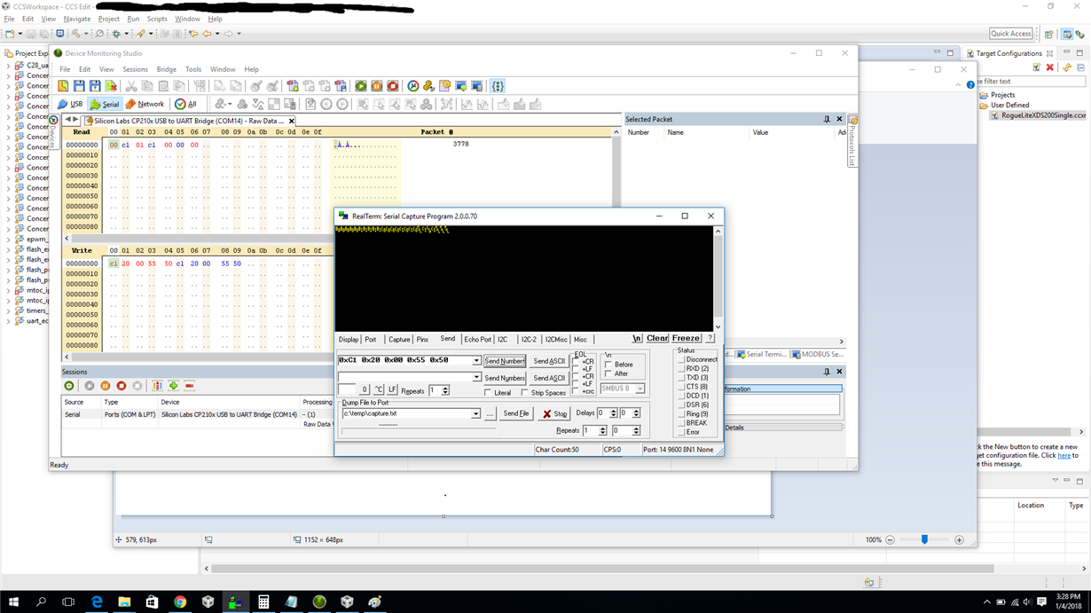
    I followed your method and I can confirm that the firmware is working correctly. I used RealTerm to send a read command to the address 0x20005550 (a variable in my program with value 01) and Device Monitor to see what the response is. The response was a C1 (the header) and the value byte which is 01. I then changed the value of the variable to 0 and sent the read command again to double check and the response was a C1 and a 00. See attached picture. The first byte 00 was sent by the target application when I started the device, don't know if it should be like that? The last two bytes, 00 00, was also when I restarted my device.

    However, if I connect the device with usb-uart to gui composer app there is no response and no data flowing on the COM port at all, according to the Device Monitoring Studio.

  • Hi Albert, 

    My apologies for delayed response. Did you by any chance try the experiment of connecting over UART connection through CCS? It would require modifying target configuration (i.e. ccxml) file to add a COM port and configure it for COM14, which is what appears to be shown in your screen capture above. If this works in CCS and the same COM port does not work in GC, then we may need to schedule a webex call to get more details. 

    Martin

  • Hi Martin

    Yes I have tried it with CCS as well. I added the com port in the configuration file and made sure to select the UART connection in the debug window. It still did not work. However, the gui did not have the red cross icons like when I select the wrong connection, but there was no response on the gui. When I was doing this I did not use the Device monitor studio to check if there was any data flowing at all, but there was definitely no communication. My target device is currently in use, I am trying to get another one setup.

  • Hi Albert, 

    Actually, the experiment that I was thinking of is slightly different. Configure CCS with jtag and uart connection, start a debug session, you would need to load symbols manually in UART and JTAG connection(i.e. click on appropriate CPU under Debug View), then switch to JTAG and run the CPU. While still on JTAG connection add a global variable that you are trying to see to expression view ( you may need to click on continuous refresh toolbar button in expression view to see it update). Now if you click on UART based connection in Debug View, you should see the same variable updating in expression view just as for JTAG. This would confirm whether rest of debug stack, which CCS and GC share, works correctly.

    This is what I would try with a LaunchPad, however, I am not sure if they same type of communication (through JTAG and UART) is possible with your device setup.

    Martin


  • Ok, I were finally able to do the test as you described. I can see the variable update when connected with JTAG but when changing the connection to UART it does not work. I have also tried to add a USB UART monitor in the GUI composer app, but then not even the JTAG wants to work.

  • Hi Martin

    I would still like to resolve this issue. Do you have any suggestion? I have executed the test like you described but still not getting communication with the UART.

  • Hi Albert, 

    This still leads me to believe that this is firmware issue of some sort. Is there an option of you sharing your target code that runs on C28? It could be a stripped down example that includes your monitor code and maybe skeleton of your app. There is an option of you privately sending files. 

    Martin

  • In my post on 30 Nov 2017 I posted the code that I added to my application to get the UART monitor working. Is that not sufficient? I can try to strip down my code, how do I send files privately?
    Also, you mentioned "your target code that runs on C28", I am not running the UART monitor code on the C28 side, I am running it on the M3 core of the concerto, does that make a difference?
  • The UART connection is working now in CCS Desktop view. I have repeated your test but this time also loaded the symbols on the UART connection. I missed that little step. So I am able to see my gui variables update over the UART connection in CCS. However it still does not work when using the cloud Gui composer app. When I run the app it seems to connect to the device, it says "COM14:9600 Hardware Connected" in the bottom left, but my target device stops running after the connection. I have not tried the UART connection from a standalone app yet, since I am having other issues there which I am trying to sort out in another thread, but that is what I eventually would like to do.