This thread has been locked.

If you have a related question, please click the "Ask a related question" button in the top right corner. The newly created question will be automatically linked to this question.

CCS/LAUNCHXL-F28027F: Trouble Debugging New Launchpad boards

Part Number: LAUNCHXL-F28027F
Other Parts Discussed in Thread: BOOSTXL-DRV8301, MOTORWARE

Tool/software: Code Composer Studio

Hi, I've been using the LAUNCHXL-F28027F along with the BOOSTXL-DRV8301. I've had 2 kits and they have always worked perfectly.

However I leant one of my working boards out so I decided to order 3 more boards to have on hand. None of the new LAUNCHXL-F28027F will debug.

They seem to flash just fine but I get the following error when I run the debugger.

I'm using CCS version 6 (Latest) and XDS100 V2)

Did something change with that board?

(All of the switches and jumpers are set to how they should be set.)

  • Steve,

    I am sorry that you are having trouble with your new LaunchPads. There have been no modifications to the board. I have a few questions to help narrow this down.

    1. When you say "They seem to flash just fine" do you mean that the LEDs flash as expected or that you are able to connect and load new code to flash?
    2. Does the XDS100 Debugger show up properly under your Device Manager?

    Thanks,
    Mark
  • Hi Mark, I mean that I'm able to load new code (Apparently thats what CCS is telling me as it starts the debug session).

    As far as the XDS100 debugger goes, I's say it in there correctly. I can literally close the debugger unplug a new board a plug in an older board and it works perfectly. But here is a screenshot of my device manager.

    Additionally I tested the XDS connection using a new board.(Below is the result . . . TLDR: connection passed)

    [Start: Texas Instruments XDS100v2 USB Debug Probe_0]

    Execute the command:

    %ccs_base%/common/uscif/dbgjtag -f %boarddatafile% -rv -o -F inform,logfile=yes -S pathlength -S integrity

    [Result]


    -----[Print the board config pathname(s)]------------------------------------

    C:\Users\usd36673\AppData\Local\TEXASI~1\
        CCS\ti\1\0\BrdDat\testBoard.dat

    -----[Print the reset-command software log-file]-----------------------------

    This utility has selected a 100- or 510-class product.
    This utility will load the adapter 'jioserdesusb.dll'.
    The library build date was 'Jul 21 2017'.
    The library build time was '19:36:41'.
    The library package version is '7.0.48.0'.
    The library component version is '35.35.0.0'.
    The controller does not use a programmable FPGA.
    The controller has a version number of '4' (0x00000004).
    The controller has an insertion length of '0' (0x00000000).
    This utility will attempt to reset the controller.
    This utility has successfully reset the controller.

    -----[Print the reset-command hardware log-file]-----------------------------

    The scan-path will be reset by toggling the JTAG TRST signal.
    The controller is the FTDI FT2232 with USB interface.
    The link from controller to target is direct (without cable).
    The software is configured for FTDI FT2232 features.
    The controller cannot monitor the value on the EMU[0] pin.
    The controller cannot monitor the value on the EMU[1] pin.
    The controller cannot control the timing on output pins.
    The controller cannot control the timing on input pins.
    The scan-path link-delay has been set to exactly '0' (0x0000).

    -----[The log-file for the JTAG TCLK output generated from the PLL]----------

    There is no hardware for programming the JTAG TCLK frequency.

    -----[Measure the source and frequency of the final JTAG TCLKR input]--------

    There is no hardware for measuring the JTAG TCLK frequency.

    -----[Perform the standard path-length test on the JTAG IR and DR]-----------

    This path-length test uses blocks of 64 32-bit words.

    The test for the JTAG IR instruction path-length succeeded.
    The JTAG IR instruction path-length is 38 bits.

    The test for the JTAG DR bypass path-length succeeded.
    The JTAG DR bypass path-length is 1 bits.

    -----[Perform the Integrity scan-test on the JTAG IR]------------------------

    This test will use blocks of 64 32-bit words.
    This test will be applied just once.

    Do a test using 0xFFFFFFFF.
    Scan tests: 1, skipped: 0, failed: 0
    Do a test using 0x00000000.
    Scan tests: 2, skipped: 0, failed: 0
    Do a test using 0xFE03E0E2.
    Scan tests: 3, skipped: 0, failed: 0
    Do a test using 0x01FC1F1D.
    Scan tests: 4, skipped: 0, failed: 0
    Do a test using 0x5533CCAA.
    Scan tests: 5, skipped: 0, failed: 0
    Do a test using 0xAACC3355.
    Scan tests: 6, skipped: 0, failed: 0
    All of the values were scanned correctly.

    The JTAG IR Integrity scan-test has succeeded.

    -----[Perform the Integrity scan-test on the JTAG DR]------------------------

    This test will use blocks of 64 32-bit words.
    This test will be applied just once.

    Do a test using 0xFFFFFFFF.
    Scan tests: 1, skipped: 0, failed: 0
    Do a test using 0x00000000.
    Scan tests: 2, skipped: 0, failed: 0
    Do a test using 0xFE03E0E2.
    Scan tests: 3, skipped: 0, failed: 0
    Do a test using 0x01FC1F1D.
    Scan tests: 4, skipped: 0, failed: 0
    Do a test using 0x5533CCAA.
    Scan tests: 5, skipped: 0, failed: 0
    Do a test using 0xAACC3355.
    Scan tests: 6, skipped: 0, failed: 0
    All of the values were scanned correctly.

    The JTAG DR Integrity scan-test has succeeded.

    [End: Texas Instruments XDS100v2 USB Debug Probe_0]

  • Steve,

    So you

    Has this software worked on a previous board?
    If you load the out of box code to the device, are you still able to connect after loading the code example code?

    -Mark
  • Mark,

    The code I run is based on motorware. I took a lab and created my own stand alone project. It works on every launchpad board I've used until this latest batch that Ive revieved.

    As I stated in my last reply, When the debug fails using one of the new launchpad boards I can shut down the debugger, connect one of my older launchpad boards, re-start the debugger and everything works. (ie: I can run the code and debug it).

    As I included in my last reply, the XDS100 can talk to the emulator hardware on the board.

    So, either my code is not being loaded in the target MCU as CCS indicates, and it's in some kind of weird state (having some or all of its flash erased) or something has changed.

  • Got it.

    Can you try to update the xds100 firmware on only one of the new LPs? Please use the following wiki. Third bullet has a link to the updater..
    processors.wiki.ti.com/.../XDS100

    After you run the utility, try your procedure again. Does this resolve the issue?

    Additionally, please find the boxes of the LaunchPads and share a photo of the white sticker label on the box. It would be great if you still have the box from the originals as well.

    Thanks,
    Mark
  • Hi Mark, well I may have a problem. The cpld programmer is saying that the device is not connected but yet my device manager is saying that it is. (See the Picture)

  • Steve,

    Have you ensured that the Debugger is not in an active session with CCS? Make sure CCS is closed while executing the command line functions.

    -Mark
  • Yes it was closed, but to make sure I double checked again. Same result.
  • This is not an issue with the XDS100 debug probe.  That you get to that particular error (and the same error each time you try) is evidence that 1) the PC is communicating with the XDS100, 2) the XDS100 is scanning successfully into the target, and 3) there's a bit set in the debug register indicating the attempt to access the register was blocked. 1) and 2) are further confirmed by the successful Test Connection results.  I don't think we're looking at an XDS100 issue but rather something going on with the target or CCS settings.

    Your CCS seems to be set to connect in Real-time mode with Polite turned on.  What happens when you hit the Rude Retry button?  Does the request work?  If so, can you disable the Real-time mode and see if you can debug the target.

  • Hi Ed, I agree with what you are saying.

    I have tried to disable polite mode with no success. I can't tell you exactly what is happening but the code does not run. Eventually (relativly quickly) I will get an error like the following picture:

    And after looking through the .map file I can confirm that there is no symbol at that address. And if I observe the variables I have in the watch window they seem to be changing on their own randomly which leads me to believe that the MCU is not under the control of the code that I downloaded. But, I have CCS set to Erase, Load, then verify the flash when I start the debugger and that process never generates an error.

    I also ran the xds serial utility and the result supports # 2 above about connecting to the xds100 (see below)

    So I'm connected enough to get that information and yet the cpld programmer is unable to open that xds device to re program it.

    Its been my suspision from the beginning that something has changed with the MCU or launchpad board because I can run older 28027 based launchpad boards and I have a 28069 based launchpad that works as well (different project and code). Only the 3 new 28027 boards I recieved do not work.

  • Mystery solved!

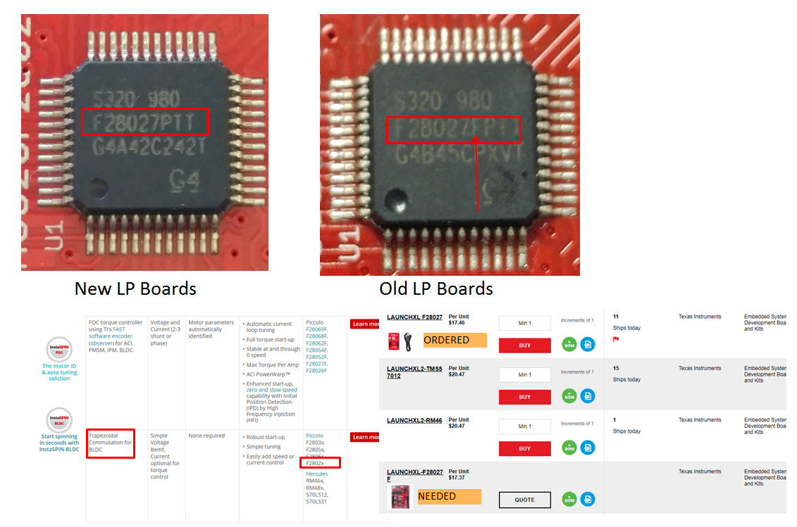
    We ordered these boards in a rush right before I went on vacation and we ordered the wrong one. I need the 28027F version for FOC instaspin. (see pic). Thanks for the help though!! Much appriciated.

  • I'm not totally convinced that this is actually why you are getting this error, but I have no convincing reason to say why.
    If you purchase n additional F28027F LaunchPad, I will be curious to see the follow up. Please post here if you get the same issue on the proper boards.

    Thanks,
    Mark
  • Hi Mark,

    Just following up. I did recieve my new 28027F launchpads this morning and they work as expected.

    Thanks