This thread has been locked.

If you have a related question, please click the "Ask a related question" button in the top right corner. The newly created question will be automatically linked to this question.

CCS/TMS320F28032: Questions in achieving interleave buck with TMS320F28032

Part Number: TMS320F28032


Tool/software: Code Composer Studio

HI,

I'M a FAE in TI, now my customer has a question.

The background is, they are trying to achieve interleave buck with TMS320F28032, buck worked in DCM mode, frequency change, and the on time Ton was constant. EPWM1A and EPWM2A was 180 degree shift, EPWM2 is slave. the problem is the EPWM2A may increase suddenly, the waveform was shown.

the yellow wave is EPWM1A, the blue one is EPWM2A, the green one is the current which was driven by EPWM2A.

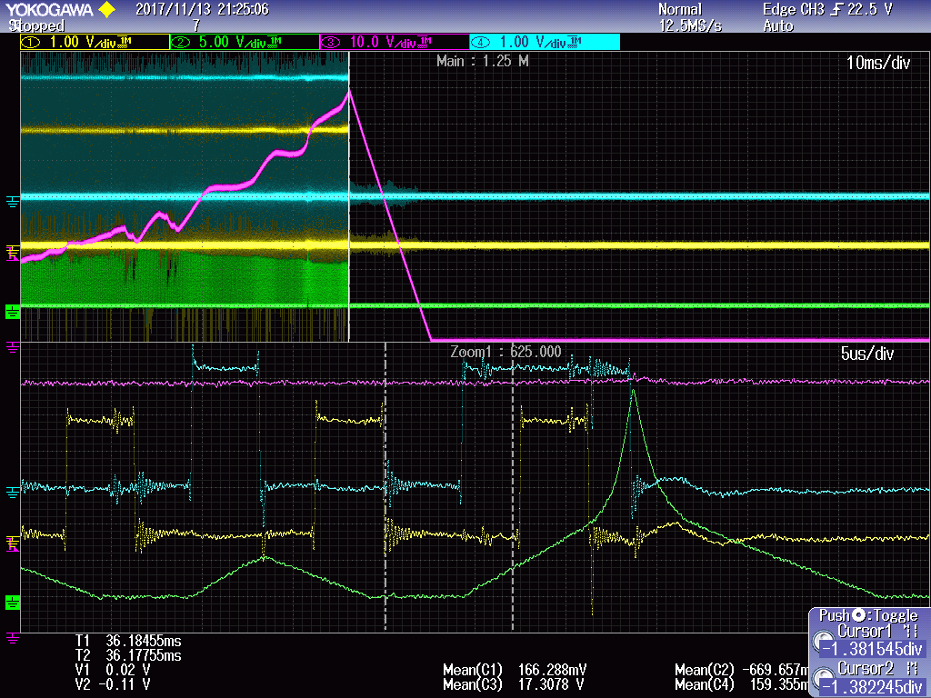
the Ton was constant, set the counter of EPWM1A give a Synchronous signal to EPWM2A when CTR=0; the EPWM2A enable the PHASE LOAD function, after receiving the Synchronous signal, set the value of CTR equal to the value of TBPHS(0.5*Ts). the 2 EPWM are both adding counter mode, CTR=0 output high, CTR=CMPA, output low.

Question: At the last rising edge of EPWM1A, the value of TBPHS was loaded into CTR of EPWM2, but at this moment, the value of EPWM2 CTR is less than CPMA, so the output is still high. the value of TBPHS was bigger than CMPA, so the CTR change from less than CMPA to bigger than CMPA, so it can't be equal to  CMPA, so the output of EPMA is still high,.

we have 3 questions:

1.is the analysis correct?

2.when use 28032 EPWM module to achieve  interleave buck in frequency change mode, is there any limitations?

3.how can we solve these problems.

Thank you very mucn

  • Hi Erwin,

    Please see my responses below:

    1.is the analysis correct?

    HN: Yes. Your analysis is spot on.

    2.when use 28032 EPWM module to achieve  interleave buck in frequency change mode, is there any limitations?

    HN: There are no functional limitations as long as the user code is written to avoid this issue.

    3.how can we solve these problems.

    HN: The solution to this problem is to avoid conditions where the PWM counter may jump over the CMPA value. For example, user code may always restrict CMPA value to be below TBPHS value.

    If this is not acceptable, the user code needs to always check the new CMPA and TBPHS values with their old values. If a change in these values may cause the PWM counter to jump over the CMPA value, the user code must change the CMPA value or the TBPHS value for one switching cycle. The code may then reapply the correct CMPA/TBPHS value in the following switching cycle. This is not a big change if a PWM ISR (interrupt service routine synchronized with the switching cycle) is already being executed every switching cycle. If it isn't, then the software should trigger a PWM ISR whenever this issue is encountered. This PWM ISR would then need to run for at least two consecutive cycles. 

    I hope this helps.

    Hrishi