Other Parts Discussed in Thread: C2000WARE
Hi
I want to configure the I2C to use no interrupt but the TX FIFO in master mode only
I need only Tx as a master, no reading (Rx). It is to control an OLED screen SSD1306
After many searches and examples I managed to have this config
The configuration
//-----------------------------------------------------------------------------
// InitI2C - This function initializes the I2C to a known state.
void InitI2C()
{
// Initialize I2C-A
I2caRegs.I2CMDR.all = 0x0000;
I2caRegs.I2CSAR = I2C_SLAVE_ADDR; // Slave address
// 90 MHz/( (8+1)(10+5 + 5+5)) = 400 kHz
I2caRegs.I2CPSC.all = 8; // Prescaler - need 7-12 Mhz on module clk
I2caRegs.I2CCLKL = 10; // NOTE: must be non zero
I2caRegs.I2CCLKH = 5; // NOTE: must be non zero
//I2caRegs.I2CIER.all = 0x24; // Enable SCD & ARDY interrupts 0010 0100
I2caRegs.I2CIER.all = 0x00; // No interrupt
// I2caRegs.I2CIER.bit.AAS = 0; // Addressed as slave interrupt enable bit
// I2caRegs.I2CIER.bit.SCD = 1; // Stop condition detected interrupt enable bit
// I2caRegs.I2CIER.bit.XRDY = 0; // Transmit-data-ready interrupt enable bit
// I2caRegs.I2CIER.bit.RRDY = 0; // Receive-data-ready interrupt enable bit
// I2caRegs.I2CIER.bit.ARDY = 1; // Register-access-ready interrupt enable bit
// I2caRegs.I2CIER.bit.NACK = 0; // No-acknowledgment interrupt enable bit
// I2caRegs.I2CIER.bit.ARBL = 0; // Arbitration-lost interrupt enable bit
//I2caRegs.I2CFFTX.all = 0x6000; // Enable FIFO mode and TXFIFO
I2caRegs.I2CFFTX.bit.I2CFFEN = 1; // Enable the I2C FIFO mode
I2caRegs.I2CFFTX.bit.TXFFRST = 1; // Enable the transmit FIFO operation
I2caRegs.I2CFFTX.bit.TXFFINTCLR = 0; // Clear the TXFFINT flag
I2caRegs.I2CFFTX.bit.TXFFIENA = 0; // TXFFINT flag does not generate an interrupt when set
I2caRegs.I2CFFTX.bit.TXFFIL = 0; // Transmit FIFO interrupt level
//I2caRegs.I2CFFRX.all = 0x0000; // No RXFIFO, no clear RXFFINT
I2caRegs.I2CFFRX.bit.RXFFRST = 0; // **Disable** the receive FIFO operation
I2caRegs.I2CFFRX.bit.RXFFINTCLR = 0; // Clear the RXFFINT flag
I2caRegs.I2CFFRX.bit.RXFFIENA = 0; // RXFFINT flag does generate an interrupt when set
I2caRegs.I2CFFRX.bit.RXFFIL = 0; // Receive FIFO interrupt level
//I2caRegs.I2CMDR.all = 0x0020; // Take I2C out of reset,Stop I2C when suspended
I2caRegs.I2CMDR.bit.NACKMOD = 0; // NACK mode bit
I2caRegs.I2CMDR.bit.FREE = 0; // Stop I2C when suspended
I2caRegs.I2CMDR.bit.STT = 0; // START condition bit
I2caRegs.I2CMDR.bit.STP = 0; // STOP condition bit
I2caRegs.I2CMDR.bit.MST = 0; // Slave mode
I2caRegs.I2CMDR.bit.TRX = 0; // Receiver mode
I2caRegs.I2CMDR.bit.XA = 0; // 7-bit addressing mode
I2caRegs.I2CMDR.bit.RM = 0; // Nonrepeat mode
I2caRegs.I2CMDR.bit.DLB = 0; // Digital loopback mode is disabled
I2caRegs.I2CMDR.bit.IRS = 1; // The I2C module is enabled
I2caRegs.I2CMDR.bit.STB = 0; // The I2C module is not in the START byte mode
I2caRegs.I2CMDR.bit.FDF = 0; // Free data format mode is disabled
I2caRegs.I2CMDR.bit.BC = 0; // 8 bits per data byte
oledInit();
oledClear();
oledGotoYX( 0, 0 );
oledPrint( "PWM" );
}
//-----------------------------------------------------------------------------
int16_t i2c1Xfer(
Uint8 address,
Uint8* wdata, int wsize,
Uint8* rdata, int rsize )
{
Uint16 i;
// I2caRegs.I2CMDR.bit.IRS = 1;
// // Make sure I2C is not busy and has stopped
// while (I2caRegs.I2CSTR.bit.BB == 1); // busy loop
// I2caRegs.I2CSTR.bit.SCD = 1; // Clear the SCD bit (stop condition bit)
// while(I2caRegs.I2CMDR.bit.STP == 1); // stop bit loop
I2caRegs.I2CSAR = address; // I2C slave address
// while (I2caRegs.I2CSTR.bit.BB == 1); // still busy?
I2caRegs.I2CCNT = wsize; // Setup number of bytes to send
for (i=0; i<wsize; i++)
{
// usDelay(1);
I2caRegs.I2CDXR = *(wdata+i);
}
I2caRegs.I2CMDR.all = 0x6E20; // Send the TX FIFO : 0110 1110 0010 0000
// I2caRegs.I2CMDR.all = 0x6620; // STT=1 : 0111 0110 0010 0000
// I2caRegs.I2CMDR.bit.NACKMOD = 0; // NACK mode bit
// I2caRegs.I2CMDR.bit.FREE = 1; // Run free I2C when suspended
// I2caRegs.I2CMDR.bit.STT = 1; // START condition bit
// I2caRegs.I2CMDR.bit.STP = 1; // STOP condition bit
// I2caRegs.I2CMDR.bit.MST = 1; // Master mode
// I2caRegs.I2CMDR.bit.TRX = 1; // Transmitter mode
// I2caRegs.I2CMDR.bit.XA = 0; // 7-bit addressing mode
// I2caRegs.I2CMDR.bit.RM = 0; // Nonrepeat mode
// I2caRegs.I2CMDR.bit.DLB = 0; // Digital loopback mode is disabled
// I2caRegs.I2CMDR.bit.IRS = 1; // The I2C module is enabled
// I2caRegs.I2CMDR.bit.STB = 0; // The I2C module is not in the START byte mode
// I2caRegs.I2CMDR.bit.FDF = 0; // Free data format mode is disabled
// I2caRegs.I2CMDR.bit.BC = 0; // 8 bits per data byte
// I2caRegs.I2CMDR.bit.STP = 1; // stop bit when CNT=0
// usDelay(1);
// while(!I2caRegs.I2CSTR.bit.SCD); // wait for STOP condition
return I2C_SUCCESS;
}
//-----------------------------------------------------------------------------
void oledCommand( Uint8 ch )
{
Uint8 bytes[2];
bytes[0] = SSD1308_Command_Mode;
bytes[1] = ch;
i2c1Xfer( SSD1308_Address, bytes, 2, NULL, 0 );
}
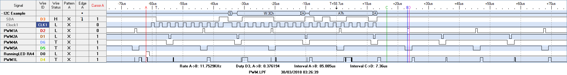
oledCommand(0xA7); //--SSD1308_Inverse_Display_Cmd : 0x80 0xA7
this order should give 0x3C as a write order (1bit shifted) then the 0x80 (cmd) then 0xA7
instead of that
I have a strange of a beginning with 8 bits clk, with 0 than the Stop than the addy in write mode, no first byte then the end byte??? and no stop bit
if I try to add the while it stops working..
Thanks for your help