This thread has been locked.

If you have a related question, please click the "Ask a related question" button in the top right corner. The newly created question will be automatically linked to this question.

TMS320F28335 PWM register


Hi @ all,

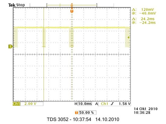
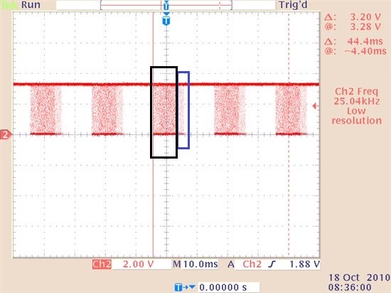
I want to use the PWM registers to actualize a signal (see figure). Which of the PWM registers I have to use?

Is it possible to configurate the PWM registers with a frequency of 25 kHz and use the deadband unit? Are there other/better oportunities to actualize this signal?

I need this signal on the GPIO0 and a complementary signal GPIO2.


With best regards,

Chris

  • The ePWM modules are very flexible and should be able to produce what you are looking for ... your best reference is the ePWM manual which can be downloaded from TI site.

  • Thank you for answering my question!

    I red the ePWM manual, but i can't figure out which of PWM registers i have to use. An answer like: "use this and that register", would be very nice.


    With best regards,

    Chris

  • Chris,

    I would suggest looking at the chopper module in the ePWM users guide SPRUGE9c, Page , it is designed to generate such waveforms. However in the simplest form it would generate a low signal where you want the high pulse. But you can use the OSHTWTH, feature? and only use it in one shot pulse(high period) and 25Khz (sustaining) mode.

    The chopper module is after the dead band control module, hence you would not be able to just invert the signal from the chopper module.

    1. Use the chopper module in only One shot pulse and sustaining mode. This is not as felxible if you need to change the duty period of the sustaining pulse.

    2. Use a not gate outside to realize the inverted output of the chopped PWM waveform.

    Regards

    Manish Bhardwaj

  • Thank you for answering my question, Manish!

    There are several problems:

    1. I want to chance the dutycycle between 1% .. 99%. I think thats impossible with the chopper module!?

    2. Is it possible to configurate the chopper module for a frequency of 25 kHz, without changing the SYSCLOCKOUT? I need the 150 MHz of the CPU!

    Is the chopper module really the only way to produce such waveforms? I will post an example code tomorrow. It works not very well. But maybe one of you could tell me why.


    With best regards

    Chris

  • I think the 20ms is too slow to do in one PWM timer cycle, it's like 4.5 times the possible counter for 150 MHz F28335.

    It would be better to treat the PWM timer with the 25KHz as the timer value, create the duty cycle in each timer oveflow, and then deal with the "full high" sections in a background SW counter.  It would be very easy to generate that waveform.


  • So, this is my solution:

    Init the PWMTimers:

    void InitEPwmTimer()
    {

       EALLOW;
       SysCtrlRegs.PCLKCR0.bit.TBCLKSYNC = 0;      // Stop all the TB clocks
       EDIS;

    // EPWM Module 1 config

    EPwm1Regs.TBPRD = 750;                           // For frequency 25 kHz
    EPwm1Regs.TBPHS.half.TBPHS = 0;                 // Set Phase register to zero
    EPwm1Regs.TBCTL.bit.CTRMODE = TB_COUNT_UPDOWN;     // Symmetrical mode
    EPwm1Regs.TBCTL.bit.PHSEN = TB_DISABLE;         // Master module
    EPwm1Regs.TBCTL.bit.PRDLD = TB_SHADOW;
    EPwm1Regs.TBCTL.bit.SYNCOSEL = TB_CTR_ZERO;    // Sync down-stream module
    EPwm1Regs.CMPCTL.bit.SHDWAMODE = CC_SHADOW;
    EPwm1Regs.CMPCTL.bit.SHDWBMODE = CC_SHADOW;
    EPwm1Regs.CMPCTL.bit.LOADAMODE = CC_CTR_ZERO; // load on CTR=Zero
    EPwm1Regs.CMPCTL.bit.LOADBMODE = CC_CTR_ZERO; // load on CTR=Zero
    EPwm1Regs.AQCTLA.bit.CAU = AQ_SET;            // set actions for EPWM1A
    EPwm1Regs.AQCTLA.bit.CAD = AQ_CLEAR;
    EPwm1Regs.AQCTLB.bit.CBU = AQ_SET;            // set actions for EPWM1B
    EPwm1Regs.AQCTLB.bit.CBD = AQ_CLEAR;
    EPwm1Regs.TBCTL.bit.HSPCLKDIV = TB_DIV2;       // Clock ratio to SYSCLKOUT
    EPwm1Regs.TBCTL.bit.CLKDIV = TB_DIV2;
    EPwm1Regs.ETSEL.bit.INTSEL = ET_CTR_ZERO;     // Select INT on Zero event
    EPwm1Regs.ETSEL.bit.INTEN = PWM1_INT_ENABLE;  // Enable INT
    EPwm1Regs.ETPS.bit.INTPRD = ET_1ST;           // Generate INT on 1st event

    //===========================================================
    EPwm1Regs.CMPA.half.CMPA = 125; // adjust duty for output EPWM1A


       EALLOW;
       SysCtrlRegs.PCLKCR0.bit.TBCLKSYNC = 1;         // Start all the timers synced
       EDIS;

    }

    the isr:


    interrupt void epwm1_timer_isr(void)
    {

       // Disable force for 4ms
       if(EPwm1TimerIntCount==0)
       {
        EPwm1Regs.AQCSFRC.bit.CSFA=0x0; //forcing disabled
          EPwm1TimerIntCount++;
       }
       // Start to force output for 20ms
       else if(EPwm1TimerIntCount==100)
       {
        EPwm1Regs.AQCSFRC.bit.CSFA=0x2; //force continuous high on output
           EPwm1TimerIntCount++;
       }
       // Set counter to zero at 24ms
       else if(EPwm1TimerIntCount==600)
       {
          EPwm1TimerIntCount=0;
       }
       else
       {
          EPwm1TimerIntCount++;
       }
      
       // Clear INT flag for this timer
       EPwm1Regs.ETCLR.bit.INT = 1;

       // Acknowledge this interrupt to receive more interrupts from group 3
       PieCtrlRegs.PIEACK.all = PIEACK_GROUP3;
       return;
    }

    It works nonsatisfying (see also figure).


    Regards,

    Chris


  • Chris,

    I woudld agree the chopper module cannot be directly used by you,

    I just created an example similar to this, and it worked correctly  on my end,

    i created two variables called pulse_duty to scale the duration of the pulsed signal, 

    volatile int    pulse_count;
    volatile int    pulse_duty;

    and then configured the EPWM2 for 25Khz operation,

    interrupt void epwm2_timer_isr(void)
    {
        pulse_count++;
       
        if(pulse_count>100 && pulse_count<pulse_duty)
        {
            EPwm2Regs.AQCSFRC.bit.CSFA=0x0;  //forcing disabled
        }
        else
        {
            EPwm2Regs.AQCSFRC.bit.CSFA=0x2; //force continuous high on output
        }
       
        if(pulse_count==500)
            pulse_count=0;
       
       
        // Clear INT flag for this timer
       EPwm2Regs.ETCLR.bit.INT = 1;

       // Acknowledge this interrupt to receive more interrupts from group 3
       PieCtrlRegs.PIEACK.all = PIEACK_GROUP3;
       return;
    }

    also make sure that your interrupt is the highest priority,


  • Hi Manish Bhardwaj, thanks for your reply!

    Could it be, that you have problems with the trigger of your scope?Just have a look at the figure!

    I have a working example, too. :) There is a simple mistake in my example code. I found it shortly after my post.

    Look at the if cases: else if(EPwm1TimerIntCount==100). Thats wrong.

    It must be: else if(EPwm1TimerIntCount==(n-1))., thus: else if(EPwm1TimerIntCount==99)


    I takes a step to long! Thats all ;)

    Now it works, I'm happy!


    Thank you all!

    Regards, Chris


  • Glad you have it working,

    In addition to this just wanted to point out that the TI BLDC motor control also uses similar PWM waveforms,

    Regards

    Manish Bhardwaj

  • hi manish bhardwaj,

    i m pradeep i m new to this epwm chopper if u have any related pdf pl forward me

    this is my mail id amapradeep@yahoo.com

    thanks and regards,

    pradeep