This thread has been locked.

If you have a related question, please click the "Ask a related question" button in the top right corner. The newly created question will be automatically linked to this question.

CCS/TMS320F28377S: How to reduce current harmonic distortion in Grid tie inverter

Part Number: TMS320F28377S
Other Parts Discussed in Thread: CONTROLSUITE, SFRA, C2000WARE

Tool/software: Code Composer Studio

Dear Concerns / E2E community members,

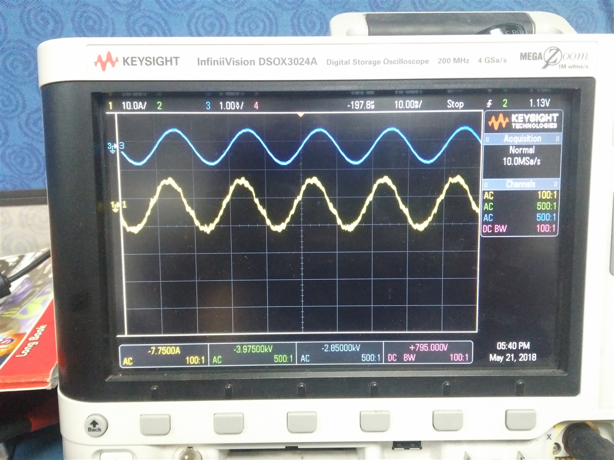
We found current harmonic distortion around 5% and current wave form in yellow colour is attached for your reference . Kindly suggest to improve further.
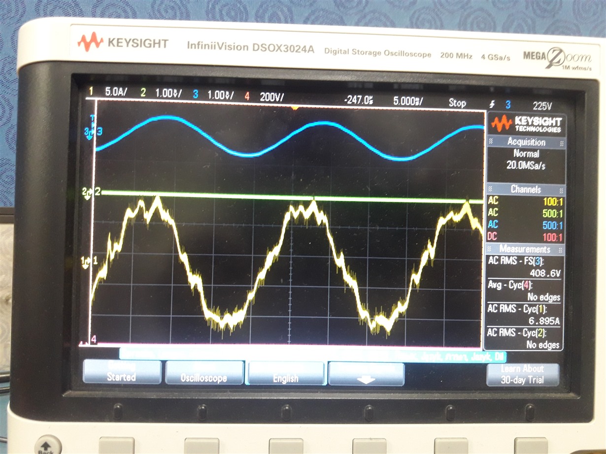
  • To evaluate if 5% is bad or not, it depends on the % of rated load. 

    Typically you can improve THD by improving bandwidth or gains at the grid frequency and its harmonics. 

  • thank you . can you please elaborate with some example in case any.
  • I don;t have a specific example to point to you, but THD appears on the current because the current is not following the reference. Which is typically because of tracking error. And tracking error can be reduced by increased control loop bandwidth.

    you might also want to check if you have a clean current reference, as that can be a result of PLL induced distortion.
  • Dear Manish,

    Thank you for your valuable suggestions. We are also suspecting on PLL mechanism. There are two theta values we can found here, one is direct Grid theta in blue colour,which is calculating by Texas SPLL_DDSRF code and second one is called Manipulated theta for which code is modified as given below to sync with Grid theta. We noticed that around 6 Deg lag in inverter generated Theta. Therefore,we have modified / manipulated code such that inverter generated theta matching with Grid theta for synchronization. Two theta codes are provided for your reference.

    Code for SPLL_DDSRF method available : "SPLL_3ph_DDSRF_F.h" (Texas ControlSuite).

    Code for Manipulated Theta:

    Manipulate_theta=spll1.theta[0];

    if((Manipulate_theta>=(0.0)) && (Manipulate_theta<=(6.175666664)))//0.08722222
    {
    Manipulated_theta = Manipulate_theta + (0.10466666);
    }
    else if((Manipulate_theta>(6.175666664))&&(Manipulate_theta<=(6.28)))
    {
    Manipulated_theta = Manipulate_theta -(6.175666664);
    }

    we look forward to receive your valuable suggestions.
  • chappidi, 

    6 degree of phase lag is 1.6% error, that is more than my expectation.

    regardless, if you want to phase shift.. please do the following 

    offset=0.104719; // (6/360)*2*pi
    
    Manipulate_theta= spll_obj->theta[0] + offset;
    
    if(Manipulate_theta>(float32)(2*3.1415926))
    Manipulate_theta=Manipulate_theta - (float32)(2*3.1415926);

    Regards

    Manish Bhardwaj  

  • good day!

    thank you, we will implement suggested code and will provide our results for your analysis.

    regards

    chappidi

  • dear manish,

    we have implemented above code and found no improvement in current harmonic distortion.
    may we get few more your valuable suggestions to enable us short it out.

    Regards,

    Bhima Prasad chappidi
  • Bhima,

    Have you schecked with SFRA how much bandwidth you have/ gain you have?

    What is the control structure you are using?

    Also most importantly what is %load at this waveform
  • Dear Manish,

    Sorry for delayed reply as we got occupied with other priorities. Thank you for your continuous support.

    SFRA:We had some errors to use SFRA tool as our Mahesh is interacting with you , thread link for SFRA is e2e.ti.com/.../681247

    Control Structure: 20kHz 2-level 3-phase VSC. The VSC converts the 670 V DC link voltage to 415 V AC and keeps unity power factor. The VSC control system uses two control loops: an external control loop which regulates DC link voltage to 670 V and an internal control loop which regulates Id and Iq grid currents (active and reactive current components). Id current reference is the output of the DC voltage external controller. Iq current reference is set to zero in order to maintain unity power factor. Vd and Vq voltage outputs of the current controller are converted to three modulating signals Uabc_ref used by the SVPWM Generator. The control system uses a sample time of 100 microseconds for voltage and current controllers as well as for the PLL synchronization unit.

    we have captured this wave form at almost 100% load (~4.95kW).

    we wish to provide few more observations by end of the day ,which is under progress and may give you some more clues for you to provide suggestions.

    Regards,

    Bhima
  • Dear Manish,

    in continuous to above information and we wish to share our other observations that  We have got basic doubt on how qualitatively capturing (reproduction ) of grid export current information.

    Please find Grid tie inverter output voltage in blue colour and load current in yellow colour when applied around 600W  resistivity load. We have tried to capture the corresponding Vd and Id to understand that how best we are able to reproduce the digital information.  We expected ideal straight line as load is resistivity.but the wave form is contains some noise information. can you please provide your analysis that acceptable or still any thing (adding filter etc) to get straight line.

    https://apis.mail.yahoo.com/ws/v3/mailboxes/@.id==VjN--dpDJWHg6b0cjdtel9OzZFyxNCLQoG6AjGPHzlGi6LH9rr5LVAgrQJWiOeuyjR4Aw0iMJb9XZfy9IvVPm1m6fxh-J5C6LyUnkpuuSevalNc/messages/@.id==AJ2GPAEwZjbaWvVsMAewwNWqjtk/content/parts/@.id==2/thumbnail?appId=YahooMailNeo&downloadWhenThumbnailFails=true&pid=2Inline image

    blue is Vd and Pu value is 1 = 800V and Orange is Id and Pu value is 1 = 10A .Hope , above information may provide you little more for your analysis.

    Regards,

    Bhima


  • Dear Manish,

    Twice i have tried to upload few wave forms (loaded ,but got message that it needs administrator approval etc.....) , which are export current ,captured at DSP I/O ports to understand and differentiate problem between Hardware and code. It looks like problem lies in the code as we are unable to get Id as straight line when inverter connected to resistive load and currents are balance and pure sine wave.
    hope you can recommend few digital filters or any suggestions. Even we have tried with notch filters, no improvement found. we got struck at this point.
    we look forward to receive your valuable suggestions.
    Regards,

    Bhima Prasad.
  • Let me check with the moderators what's going on..
  • Dear Manish,

    Thank you for your valuable suggestions.

    Please find attached results of GTI,which are taken at different ISR frequencies like 25usec,50usec and 100usec. Switching frequency is 20kHz.We have noticed improvement for different ISR values. We fare feeling that we may be failing to implement code properly as we are not seeing influence of different ISR and found same results for all above ISR frequencies.

    We look forward to receive your further instructions..

    Regards,readings at different isr freq.rar

    Bhima Prasad

  • Bhima,

    did you chnage your coefficiencts for the control loop as you changes from 25usec , to 50usec to 100usec ??

    Also, did you make sure you triggered ADC faster when the ISR is running faster ?
  •   Dear Manish,

    Sorry for delay in response,  we have changed coefficients for control . however once again we have optimized and again captured wave form and found little improvement  for 25us ISR operation. i.e iTHD consistence in all phases  (6.1,6.2,6.1% ) at 5kw 100% load and pf is unity in all phases .  The  corresponding code  and images  attached for your reference.  

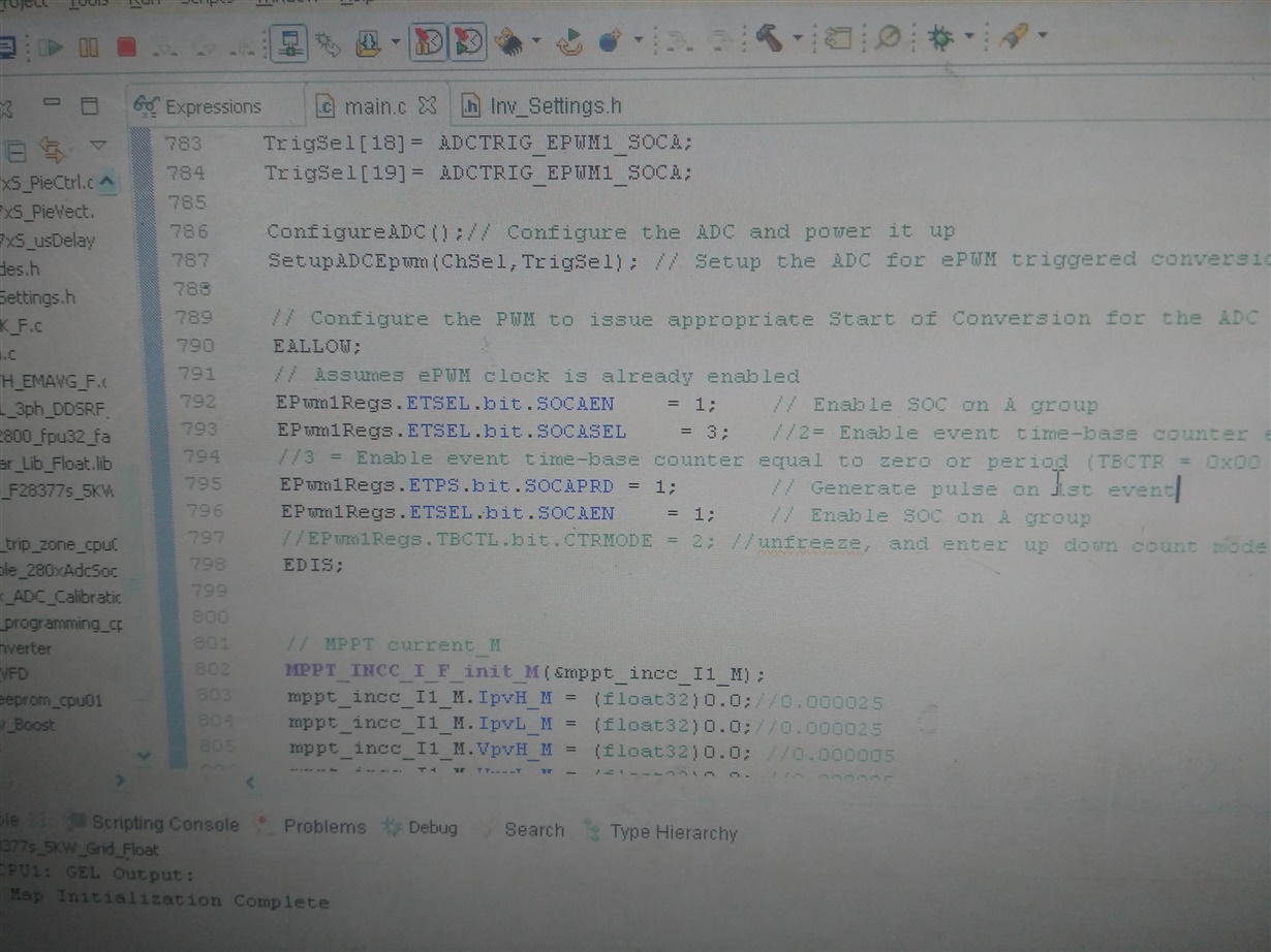
    ADC is sync with PWM. We are able to operate ISR at max ADC  is 40kHz (25us). We struggle to increase ISR more than 40kHz as ADC is sync with PWM. Is there any other way to increase ISR frequency more than 40kHz as we wanted verify ithd results for higher frequencies as advised by you.

    Please   provide your analysis to reach target ithd <3%.

    Thanks and Regards,

    Bhima Prasad.

  • Bhima,
    1. Please check with SFRA and see how much badnwidth do you have
    2. Can you put a haromic analyzer and tell where the harmonics are ??

    I think currently you are only running ABC-DQ0 on the grid fundamental, PI in ABC-DQ0 is a PR controller in frequency domain, which means the bandwidth at harmonics is not that great and that can cause harmonic distortion.

    see fig 41 in www.ti.com/.../tidub21b.pdf

    and you may have to run additional ABC-DQ0 controllers.
  • For double update i.e. running ISR at 40kHz, you will need to configure two different set of ADC conversions for the current. Read a different register/ alternate register each time .. one is trigerred at PRD other at ZRO
  • Dear Manish,

    Happy to  get immediate response and note your suggestions,

    1) Currently we unable to run SFRA. we definitely use this tool,which is faster and accurate for regulators tuning.

    2) We had problem with 5th harmonic.

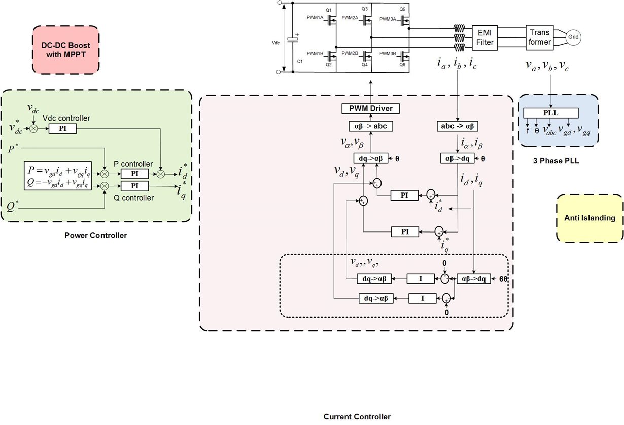
    3) we would like  to modify (added additional blocks as shown in shadow) our control flow as per attached document  to address 5th harmonic issue.

    4) we will configure ADCs also as per your suggestions i.e one trigger at PDR other at ZROPI for 5th Harmonic.pdf

  • one attachment is missed in earlier reply

    regards,

    Bhimaadd5thharmonic pll.pdf

  • Bhima,

    there are certainly different ways to implement this compensation,

    you can refer to www.amazon.com/.../ref=sr_1_2

    to find ways to do this,

    you may not need to run the 5th harominc PLL , it can be anough to just take 5omega out of it.

    I'll be honest my own experience in using this for three phase converters is less, so i'll need to think about this more.
  • Dear Manish,

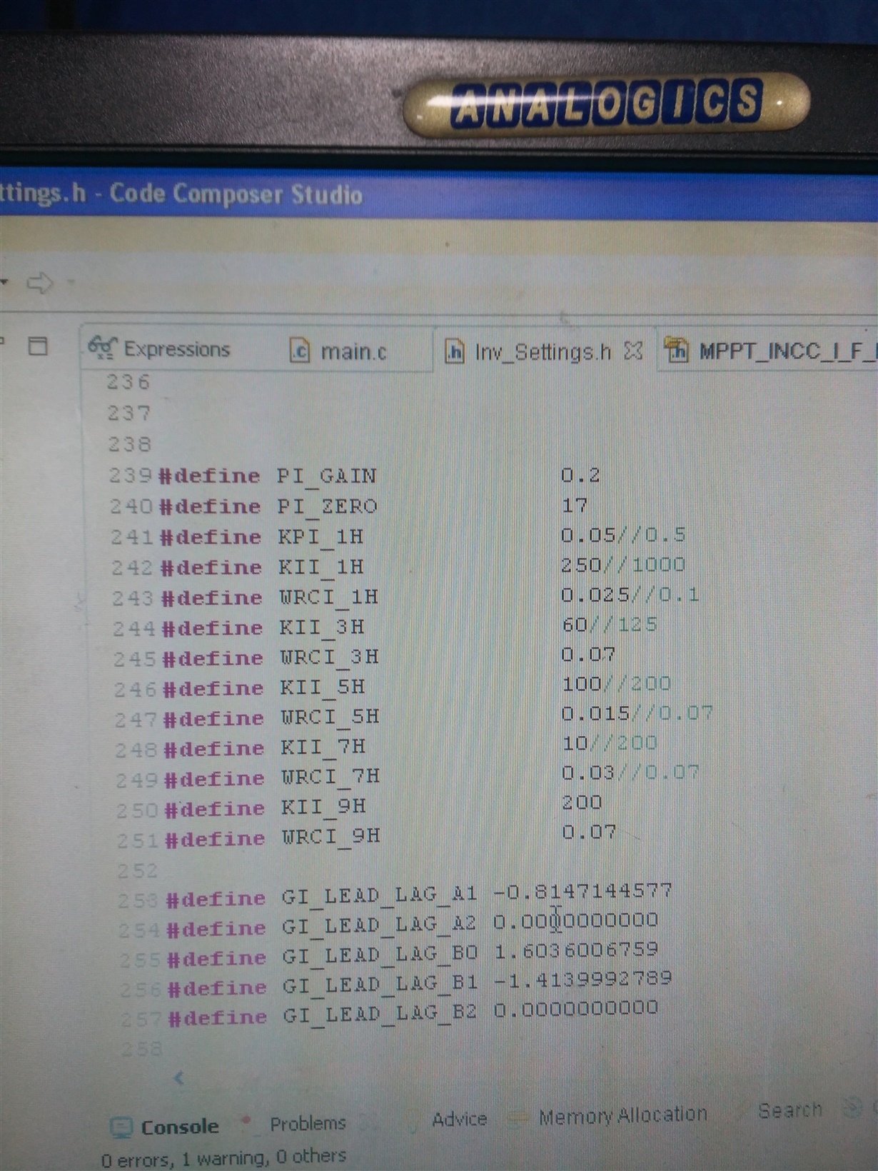
    We found improvement with your inputs. We have added DF22 controller to eliminate significance of  3rd,5th harmonics.  We  manually (trial and error) tuned KII,WRC1 coefficients till get the optimized Ithd and document is attached for your reference.Now we are getting Ithd around 4.7 to 5.5% (<6%) .Our object is to bring down ithd <3%. what more needs to be done.

    I am expecting we can fine tune further with help of SFRA tool. But we are facing error while using SFRA. First,we wish to sort out the SFRA issue to make use of the tool properly. Please suggest.

    Please clarify our doubt that  SFRA can be used  for fine tuning of PI controller of all sections of GTI. because we are  basically using two PI controllers for GTI i.e one for Voltage regulator to produce Id_ref and second one for Current PI controller. Now we are adding DF22 controller for 3rd,5th ,7th +++ for elimination of harmonics.  I think we need to tune one after other or is there any procedure.

    Regards,

    Bhima Prasad

  • Bhima,

    I am glad things are going in the right direction.

    Yes for SFRA you will have to tune one loop at a time.

    For PR controllers as you have to measure the loop gain at the grid frequency, you will need to run the inverter under DC conditions.

    I am not sure why you are having issues with SFRA, we do have examples running on F28377D, maybe you can compare the sequence of code between these known good and what you have.

    C:\ti\c2000\C2000Ware_DigitalPower_SDK_1_00_00_00\solutions\tidm_hv_1ph_dcac\f2837x\gridconnectedinvlclfltr

    Regards
    Manish Bhardwaj
  • Dear Bhardwaj,

    Thank you for your continuous support and motivation.

    we have good news to share with you, Just Now errors are cleared and SFRA tool working fine with IQ format code. earlier,i think reason for not working of SFRA tool could be due to change of SFRA code to floating point as we wanted to match with our code format i.e in floating point. am i correct Dear Bhardwaj?.
    Results on open loop will be conducted tomorrow to find out closed loop coefficients and will shared the results.

    Thanks and Regards,
    Bhima.
  • Dear Bhardwaj,

    GTI results with SFRA tool:

    Load = Grid =5kW (full load),  GTI_Switching Frequency:20kHz, Grid frequency:50Hz

    FRA settings = Default =Freq Vector length =100, start freq =100Hz,Steps per decade =40,injection amplitude =.01

    Generated CSV file.

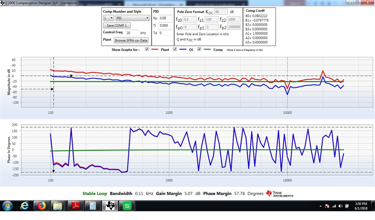
    Tuned Kp is 0.08 and Ti = 0.09,Ki=8 till we get bandwidth=0.11kHz,Gain margin =5.07dB,Phase margin=57.78Degrees (may we know what are recommended values of BW,GM and PM for main GTI plant)

    we have embedded these values in code and observed that ithd is around 11% at 5kW grid load.

    I am thinking that some thing we are missing to use this SFRA tool properly. May i get some clues to  make use of this tool properly.

    Regards,

    Bhima Prasad.

  • SFRA plot looks ok, as you are using ABC-DQO transform at the grid frequency. you probably don;t need much bandwidth. The numbers you are getting look stable.
  • Also, based on the plots it looks like you do not have much gain as well , the OL gain at 100Hz is barely above zero,

    I think the following will help

    1. Move to double sample, this will improve the phase margin with SFRA
    2. Once you have improved phase margin, you can design a lead lag compensator to improve the bandwidth by trading off some phase margin, which will improve the gain in the OL curve.
  • Thank you Bhardwaj,current_control_3ph_GTI.pdf

    we will try above and provide you the results.

    however we wish to share our current regulator schematic as attached and other issues for your guidelines and clarifications. We are facing two issues that one is we are unable to run SFRA tool in float format, Second one is we are unable to find 3rd/5th Harmonic (DCL_DF22) controller code in  IQ format.can we get DCL_DF22 code in IQ format.

    Regards,

    Bhima Prasad

  • Dear Bhardwaj,

    Please note significance of different harmonic influence.

    can you Please provide us DCL_DF22 code in IQ format. 1. Move to double sample = please elaborate


    Regards,

    Bhima

  • results are missed in earlier reply

  • sorry results again not attached .please find attachmentharmonic_thd_inverter.pdf

  • chappidi,

    1. DCL Code in IQ format:  DCL lib is not ported to IQ format and there is no plan to port it to IQ format.

    you can use the CNTL_2P2Z module which is in controlSUITE under solar library, note there is a sign change in the CNTL_2P2Z module

    Here is the inverter example that uses it:

    C:\ti\controlSUITE\development_kits\HV_1PH_DCAC\v1_04_00_00\f2837x

    2. I am not sure if your harmonic compensation is correct. Unfortunately I myself have not done this for three phase inverters where this is in DQ domain.

    There are a couple of options to do this

    Following is one suggestion to achieve this.

    The way you have it , will not work because of the DQ transform, that method that i showed you for the single phase works if the control is in abc domain. It will work very differently in the DQ domain

  • Also, one more thing i wanted to higlight is that for 5th harmomic you will only have negative sequence and for 7th positive sequence.. hence the theta used must be multipled approriately when used in DQ domain.
    For example in the above image i multiply by 6 *theta, so when it is done in dq domain , (7w-w) -> 6w in dq
    for the 5th harmonic, (-5w-w)> -6w

    so both the 5th and the 7th generate 6w, the sequence is different and you will need two of the harmonic compensator blocks in dq domain that i have shown above.

    Also for the 5th harmonic
    www.allaboutcircuits.com/.../
  • Dear Bhardwaj,

    Thank you for your valuable inputs, sorry we took more time to respond due to understanding, implementation and other priorities. we have implemented harmonic control in dq domain as suggested in above schematic. we understood implemented new block (shown in shade) is responding means we are able to see some outputs. Please find an attached control ,which is added to our existing control by considering above schematic. Also find results in graphs at appropriate points as provided in pdf.

    but we don't find improvement in performance i.e reduction in harmonic. can you please verify our control schematic and provide your suggestions .

    Regards,

    BhimaGTI_control.pdfharmonic_graphs.pdf

  • Hi,

    I am surprised you did not see improvements, however, at this point, I am not sure what I can recommend more on this topic as this is the limit of my knowledge on this subject. 

    I believe you may want to get help from a consultant etc, who knows more than me. Also, considering this is system level issues (not device level) this falls outside the scope of the support we typically offer on the forum. 

    We will be conducting tests on 

    and we will be more knowledgeable after we have conducted full tests on that design and have practically experimented with some of these techniques.

    I do know this does not solve your issue, but to your original question, i have provided several suggestions and pointers (even though it does not fall under the support task, because of not dependence on the device or a solution that we promote/have).

    I will close this thread, if you have any other issues that are device related please create a new thread. 


    regards

    Manish Bhardwaj