This thread has been locked.

If you have a related question, please click the "Ask a related question" button in the top right corner. The newly created question will be automatically linked to this question.

CCS/TMS320F28377S: Does interrupts (such as ADC, PWM etc interrupts), interrupt the EMIF read or write sequence?

Part Number: TMS320F28377S
Other Parts Discussed in Thread: C2000WARE

Tool/software: Code Composer Studio

Hi,

I am using TMS320F28377S processor for my project work. I have configured this DSP to a FPGA using EMIF interface in asynchronous mode (16-bit).

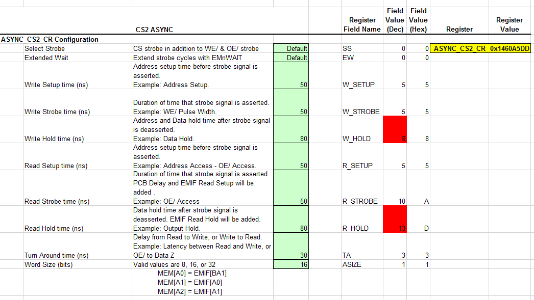
I have configured the EMIF with the following configuration to synch with FPGA.

READ_SETUP_TIME 4 (50nsec)

WRITE_SETUP_TIME 4 (50nsec)

READ_STROBE_TIME 4 (50nsec)

WRITE_STROBE_TIME 4 (50nsec)

 READ_HOLD_TIME 7 (80nsec)

WRITE_HOLD_TIME 7 (80nsec).

TA (TURN AROUND TIME) 3 (40nsec)

Max Wait Count 80h

However, when i am seeing 0xFFFF in between while reading data size (126Kbytes) from FPGA  in the rate of 170 *16 bits per read.

Such as, each read can take 0.6-0.7 usec (16-bit) which can be   0.7usec for 126Kbytes = 38.7usec. 

I suspect, an interrupt from processor could have caused the read operation or EMIF read error.

Please find the data below. The 0xFFFF is un-known data.

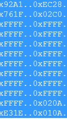
Please suggest me a possible solution or debugging method to trace out.

Thanks & Regards

Chandra

  • Chandra,

    A CPU interrupt can certainly interrupt the CPU while it is reading a block of data from EMIF using a loop.  You can possibly profile this behavior by toggling a GPIO pin inside of your ISRs to see if they coincide with the EMIF reads.

    You have two general approaches for protecting EMIF block reads if it is interrupts interrupting:

    1. Disable interrupts when reading EMIF data (probably not desirable), or
    2. Use the DMA or CLA to perform the read (recommended)

    There are emif_dc_* examples in C2000Ware that you can reference for setting up DMA or CLA transfers.

    -Tommy

  • Hi Tommy,

    Thanks for the quick response. Its a good idea to use DMA. Currently i am reading the DMA approach to use in my project. Could you please suggest me on the below thought for better understanding on EMIF with interrupts.

    I think, a single EMIF read (single read call action, which is SETUP, STROBE and HOLD) can not be interrupted. If so, while reading a block of data using EMIF in a loop, a CPU interrupt can interrupt the read, then CPU can halt the interim read operation, serve the interrupt and resume the EMIF read. Based on this, if a EMIF read can complete the block of read with out any obstruction.

    Please correct me if the above mentioned is incorrect.

    Thanks

    Chandra

  • Chandra,

    Yes, a single EMIF asynchronous operation is atomic.  When a CPU read instruction is issued, it will stall until the data is returned from EMIF.

    So in the case of the read loop, when the interrupt is generated, the CPU will be stalled until the active EMIF read operation is completed, and then it will context switch to service the interrupt.  After servicing the interrupt, the CPU will resume execution after the EMIF read.

    -Tommy

  • Hi Tommy,

    Thanks for the update and confirmation.

    As per the last shared information, CPU will context switch to service the interrupt from EMIF read.

    So, in this case there won't be any corruption of data because of Interrupts. In that case, why we should go for blocking interrupts while reading a EMIF in a loop.

    Please clarify me on this.

    Regards

    Chandra

  • Chandra,

    I was under the impression that you had determined the problem to be interrupts breaking the CPU read loop.

    Is the FPGA emulating a true asynchronous memory interface whereby one memory word is placed on the bus based on the address presented by EMIF? If this protocol is followed, then the CPU read loop should not have any issues with interrupts. I would only expect issues if there is some custom implementation.

    -Tommy
  • Hi Tommy,


    Thanks for the response.
    My assumption was the interrupts breaking the CPU read loop. To confirm that i have blocked the interrupts during the read & i am able to read all chunks of data with out any wrong data. In that case i thought that, interrupts may be an issue. However, when i am analyzing the issue for details, i have confused my self how interrupt can cause this. So its coming to a dead-lock situation for me. Due to this reason i have aproched e2e. I should not use DMA or CLA as per project limitations.

    I have confirmed with FPGA developer about the true asynchronous memory interface, they have confirmed that no data can be placed on the bus until a read request received. And i have confirmed with CS (Chip Select) pin setting High and Low states according with CPU-EMIF.
    We have observed an extra 38nsec-50nsec of STROBE period while performing a read operation.
    Hope Extended Wait can handle this.

    I have followed the timing calculation provided by TI and FPGA developer team. Please find the details below (Is this custom implementation?)

    EMxCLK = 10nsec

    EMIF configuration is :
    Asynchrounous Configuration (ASYNC_CS2_CR),
    Select Strobe = 0 (Normal Mode)
    Extended Wait Enabled,
    Asynchrounous Bus Width = 1
    EM_WAIT Polarity = 1,

    Parameter Value (ns)
    SETUP 50
    STROBE 50
    HOLD 80

    R_SETUP/W_SETUP = SETUP * fEM1CLK -1
    50ns *100 MHz -1 = 5-1 = 4
    R_STROBE/W_STROBE = STROBE * fEM1CLK -1
    50ns *100 MHz -1 = 5-1 = 4
    R_HOLD/W_HOLD = HOLD * * fEM1CLK -1
    80ns * 100 MHz -1 = 7

    Hope this information can give some clarity. Any suggestions greatly appreciable.


    Regards
    Chandra
  • Chandra,

    Can you clarify what you mean by "We have observed an extra 38nsec-50nsec of STROBE period while performing a read operation"?

    The EM_WAIT function is generally not used for devices with determinate response times.  I assume that your FPGA has fixed cycle time behaviors.  Would it be possible to increase the STROBE period to satisfy the FPGA response time instead?

    Does your EMxOE signal have the expected assert duration?  It will be good to confirm that the EMIF is really operating at 100MHz.

    There is also an EMIF configuration tool in C2000Ware that you can use to double-check your register settings:

    \ti\c2000\C2000Ware_XXXX\boards\TIDesigns\F28379D_EMIF_DC\C2000-EMIF_ConfigurationTool.xlsx

    I would also recommend that you view the FPGA reads on a scope to confirm that the data looks good on the pins.

    -Tommy

  • Hi Tommy,

    Thanks for the information and tool.

    i have used the (excel file to calculate EMIF values) tool to update the Setup, Strobe and Hold timings. Please find the observation below.

    As per the FPGA, 

    Write Setup Time, Write Strobe Time, Read Setup Time, Read Strobe Time is 50nsec.

    Write Hold time, Read Hold Time is 80nsec.

    Please find details below:

    Where, Write & Read Hold time are going more than the bit field limit (R_HOLD, W_HOLD are 3bit range 0-7). So, i have opted to use W_HOLD & R_HOLD values to 7h. Which is less than expected. Same for TA.

    However, I am using the below calculations for SETUP, STROBE, HOLD & TA timings

    R_SETUP/W_SETUP = SETUP * fEM1CLK -1

    50ns *100 MHz -1 = 5-1 =4

    R_STROBE/W_STROBE =  STROBE * fEM1CLK -1

    50ns *100 MHz -1 = 5-1 =4

    R_HOLD/W_HOLD = HOLD *  fEM1CLK -1

    80ns * 100 MHz -1 = 7

    Where  fEM1CLK  is 100MHz.

    Please suggest me the impact by using the values which is less than calculated value. Please suggest me an alternate to resolve this?

    I have captured the FPGA Read Write Timings, Please find details below. The Blue color marked is the "additional 38-50ns before end of STROBE time". Which means FPGA is already providing an extra STROBE time.

    Unfortunately, we don't have provision to change FPGA timings (Limitations).

    Is this timing can impact on data loss? Suggest me any possible solution to over-come this timing. Any suggestions greatly appreciable.

    Please let me know if any information required.

    Thanks

    Chandra 

  • Chandra,

    TA will not help you much unless the FPGA has a response time limitation for recognizing back-to-back operations.

    Can you use a larger STROBE value?  The data is expected to be valid at the end of the STROBE period, and the STROBE register field is 6-bits wide so you can have up to (63+1) cycles of delay for the data bus to be valid.  That should be more than enough based on your wave forms.

    I am not able to tell which of your signals is FPGA-input or FPGA-output so please help to clarify that if increasing STROBE is not helpful.

    -Tommy

  • Hi Tommy,

    We have solved the issue. There is no issue regarding FPGA-EMIF. It is internal bug, we have cleared.
    Thanks a lot for your great help and suggestions.

    Regards
    Chandra