This thread has been locked.

If you have a related question, please click the "Ask a related question" button in the top right corner. The newly created question will be automatically linked to this question.

CCS/TMDSECATCNCD379D: 2837x, EtherCAT, TwinCAT3.1

Part Number: TMDSECATCNCD379D
Other Parts Discussed in Thread: CONTROLSUITE, TMS320F28379D, TLK110

Tool/software: Code Composer Studio

When I debug the TMDSECATCNCD379D, encounter 3 questions ,as belows:

1、TMDSETHERCATCNCD379D project choose option 2 which is _F2837xD_CCARD_EFMIF_RAM. then build project, press run->load program and run program.

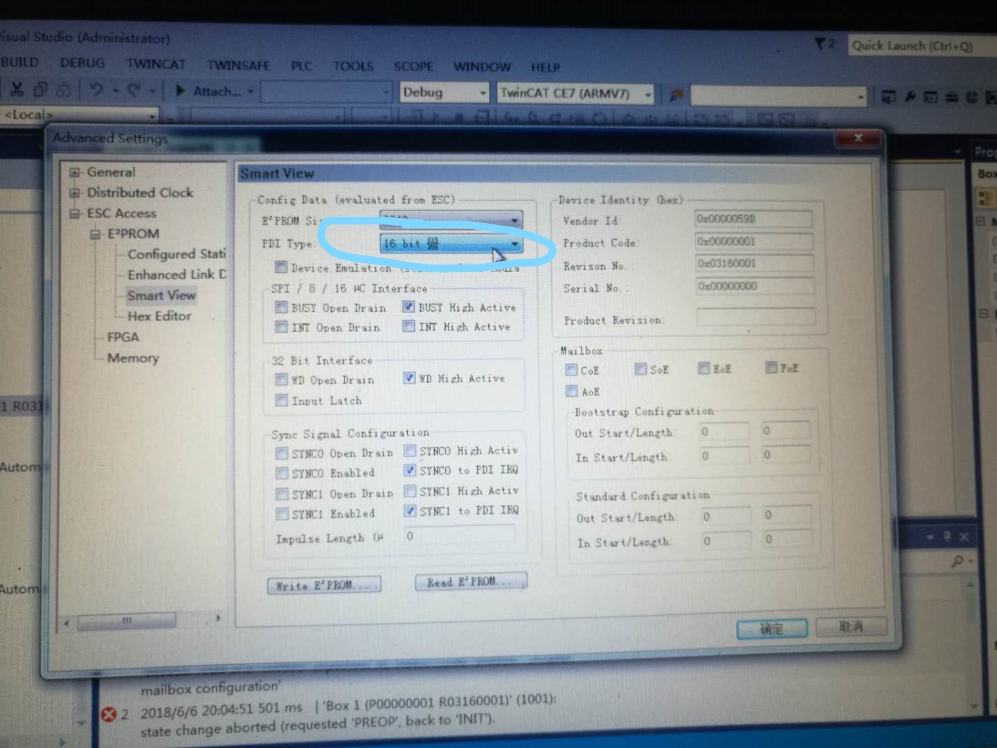
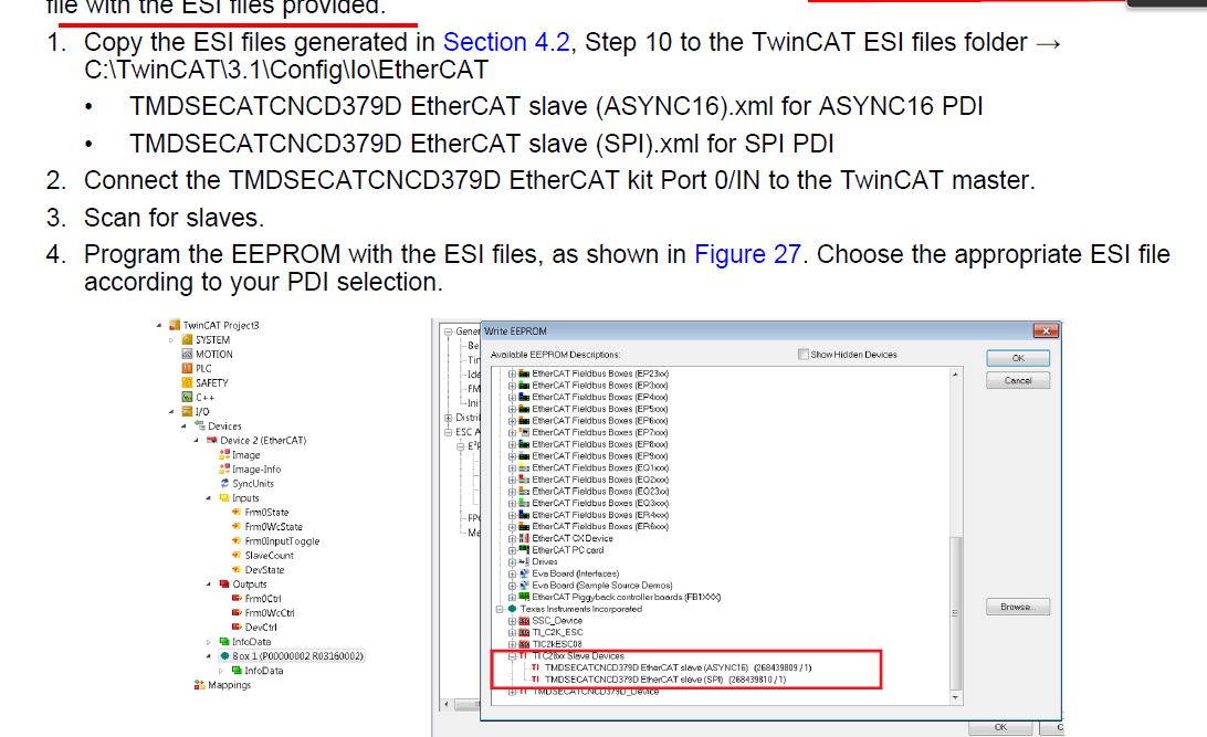
BOX1 had been scaned in TwinCAT3.1 .When setup advanced settings to write eeprom, it always hints no responding and can display nothing like figures shown. What am i doing wrong?

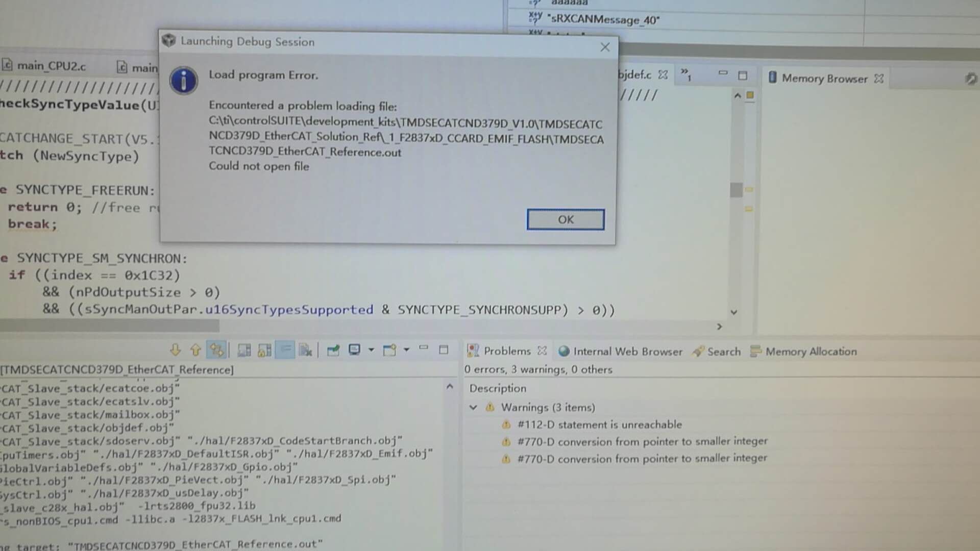
2.  I want to choose the project option 1 flash or 2  ram  ASYN16 .But another problem comes out. When I press dubug button, windows form appear to give a session"load program error".

of course, CCS give another 3 warning under the problwm window. I don not know how to fix it .

My CCS is Version: 8.0.0.00016 .

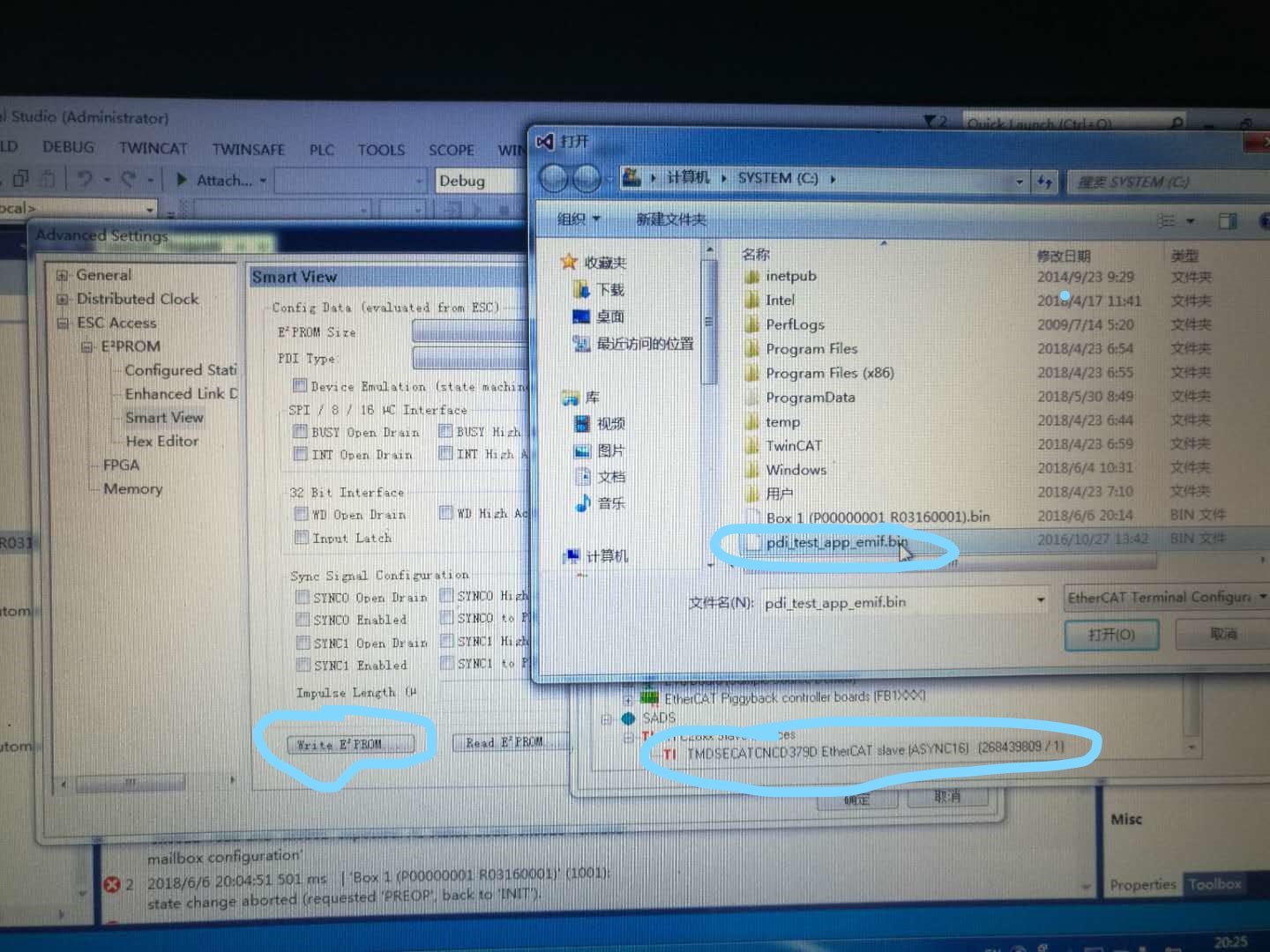
3、From spruig9,Page20 shows that program eeprom need to choose ESI ,this means choosingTMDSECATCNCD379D EtherCAT slave (ASYNC16) .xml.

SPRUIF9 P19 No.3 show that Write eeprom then to choose pdi_test_app_emif.bin.

so which one is correct to write eeprom?

  • Hello

    1. Can you select read the contents? This will populate that window. Make sure you waiting for EEPROM to program, there's a progress bar at the bottom, it takes a little time.
    2. It sounds like the project didn't build correctly and hence no OUT exists. You can ignore those warnings.
    3. The PDI test app only requires the eeprom BIN file, which populates the minimum content into the EEPROM. For the echoback or solution ref, you should use the XML file as described in the guide. This EEPROM files contains all the information needed for the master to know the outputs and inputs.

    Best regards
    Chris
  •   Chris, thanks for reply.

    1. I can read the content of EEPROM , but  I think it is not correct and different from pdf file. The picture is as pic1, pic2 shows the writing EEPROM progress:

    2. The project can be build and debug , generate .out file , a good news for me.

    3.I guess because of wrong info. read from eeprom , Twincat can not scan out box which has Ti lable.

    CCS 8.0;

    SSC 5.12     I am not sure it affects the result.

  • Hello

    I'm seeing anything wrong in those images.
    Can you please clarify and describe what your current issue is? You should power off and power on the device after loading EEPROM.

    Please use SSC 5.11.

    Best regards
    Chris
  • Chris, thanks a lot.

    echoback dome can be done successfully. But PDI HAL test demo fail . I have some questions to ask.

    1. echoback demo : What is difference between .xml in the C:\ti\controlSUITE\development_kits\TMDSECATCND379D_V1.0\TMDSECATCNCD379D_EchoBack_Demo and .xml which  is used by myself through SSC 5.11. If It is the same , I can use .xml generated in C:\ti\controlSUITE\development_kits\TMDSECATCND379D_V1.0\SSCToolC28xPatch.

    2.echoback demo:If I Choose project build configuration option 1 flash , and dubug . CCS shows the main function ,then i must press F8 to run. In my opinon, . out  is download into flash, then  I can power off and power on ,but no need to connect jtag ,and it can automatically run well.      

    3.  pdi_hal_test demo:

    I can find esc memory address ,and enter into addr.1000 and addr.1002 . then I press the "write " button , the red number'1234' and '5678' change into black number. But at the same time ,CCS is running pdi_hal_test demo ,but have no response . test_address and dtest-data show nothing. 

    I guess when ESC RAM WRITE ,then project will halt at some line?

     how to excute readding  from PDI to ESC in detail? 

    4.   I want to develop my board and protocol using EtherCAT, I do not kown what i can refer from echoback demo and pdi_hal_test_demo.

    how can I  generate .xml and .bin file if I only use my hardware and borad designed by myself , the core is TMS320F28379D, esc is ET110,SSC 5.11 ,CCS 8.0?

    I find when I import C28xx_Config into ssc ,it show many choices to choose.But four options are  about TMDSECATCNCD379D.I do not think the four ones are my answers , If I use SSC to generate .xml needed by twincat3.1 , how to choose or do next?

    Can you give me some guidance about the process ? 

    5. slave stack code is not used in the pdi_hal_test demo ,but used in echoback demo ,I do not know why?

  • I need help to develop ethercat using 28379d and use my hardware ,design application protocol on ethercat. 

    Thank you .

  • Hello

    EtherCAT dev flow at a high level: e2e.ti.com/.../real-time-control-meets-real-time-industrial-communications-development-part-3

    1. Those XMLs are essentially the same. I recommend using the ones with the appropriate project as defined in the user guides
    2. Ok that sounds good
    3. You have to setup breakpoints in the ESC_setupPDITestInterface() to see test_address and dtest_data. You can step through that function, change values via master, and see the changes reflected in CCS.
    4. You don't need .bin, that is only for the HAL test app. You will generate the XML as you have through the guide and integrate etherCAT into your project as shown in the reference project which uses the stack source. You will choose the XML (either SPI or EMIF) based on how your board will be setup to use the ET1100. The other two just also include the demo project. Refer to ETG site on more about the SSC and etc.
    5. The PDI Hal Test demo doesn't have stack, it purely a test of the HAL functions and reading/writing to memory. Echoback demo has the stack for full etherCAT operation.

    Design files are at: www.ti.com/.../TIDM-DELFINO-ETHERCAT

    Best regards

    Chris
  • Chris,Thank you for reply and it helps me.

    I will try to go on pdi hal test demo , and  develop Ethercat using my bord later.

    When I use the board designed by meself connectting to ET1100(asyn 16), I can chooses below option.But I wonder it is noly used on TMDSECATNCD379D ,because it is writen on "TMDSECATNCD379D kit ". how to choose?

  • Yes, it is referring to kit since F28379D requires the etherCAT daughter card to work. That stack code should be sufficient if your board is wired the same as the kit.

    Best regards
    Chris
  • if EtherCAT daughter card is not used,and I userd EtherCAT circuit by meself refered to beckhoff documents, "Ti C28XX sample
    with ET1100 ESC(ASYNC16 PDI) on TMDSECATCNCD379" is the option which I can choose? I think maybe it is not suiteable for my ethercat hardware designed by meself.

  • Yes, it is. This provides the changes to support running on C28x and the setup to interface with the ET1100 through EMIF.

    Best regards
    Chris
  • Chris:
    Your reply is very helpful.

    Now there is a problem in my hardware.
    My circuit is completed, I use TLK110 as PHY , ET1100 as ESC , 24LC16 as EEPROM.

    The first step is to scan my Ethercat device in the TwinCAT3.1. But there is no new box.
    I found that both TLK110 and ET1100 are needed to initialize. What I need to do is to download the first 8 words of the SII into EEPROM.
    I refer TMDSECATCNCD379 circuit and found that ET_SCL and ET_SDA pins of EE2PROM are pullup externally and connected to ET1100 and 28739D.
    I guess that SCL and SDA pins are controller by 28379D to write the first 8 word into EEPROM at the first time while EEPROM is blank and not used to download by external programmer.
    My understanding is correct?
  • That's correct.

    Best regards
    Chris