Hi expert,
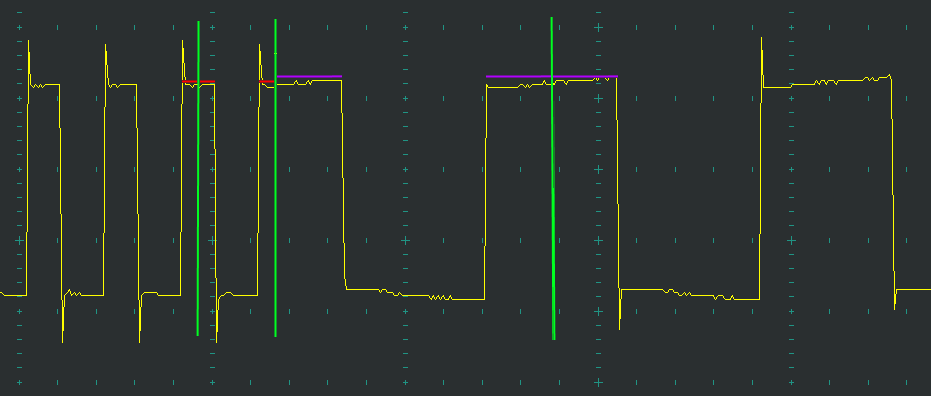
I am trying to make 50% duty square wave and switching its frequency between 70kHz and 250kHz on F280049C LaunchPad use both PWM5 and PWM6. I made a constant 40kHz interrupt using PWM4 and want to update the PRD, CMPA and CMPB value at the PWM5's counter equal zero event. Shadow loading is enabled on period and for compare values the shadow load mode is enabled by default.
When I doing test, there is always a inter-frequency wave in between the 70kHz and 250kHz like below.

//#############################################################################
//
// FILE:   epwm_ex2_updown_aq.c
//
// TITLE:  ePWM Action Qualifier Module - Using up/down count.
//
//! \addtogroup driver_example_list
//! <h1> ePWM Up Down Count Action Qualifier</h1>
//!
//! This example configures ePWM1, ePWM2, ePWM3 to produce a waveform with
//! independent modulation on ePWMxA and ePWMxB.
//!
//! The compare values CMPA and CMPB are modified within the ePWM's ISR.
//!
//! The TB counter is in up/down count mode for this example.
//!
//! View the ePWM1A/B(GPIO0 & GPIO1), ePWM2A/B(GPIO2 &GPIO3)
//! and ePWM3A/B(GPIO4 & GPIO5) waveforms on oscilloscope.
//
//#############################################################################
// $TI Release: F28004x Support Library v1.05.00.00 $
// $Release Date: Tue Jun 26 03:10:30 CDT 2018 $
// $Copyright:
// Copyright (C) 2018 Texas Instruments Incorporated - http://www.ti.com/
//
// Redistribution and use in source and binary forms, with or without
// modification, are permitted provided that the following conditions
// are met:
//
//   Redistributions of source code must retain the above copyright
//   notice, this list of conditions and the following disclaimer.
//
//   Redistributions in binary form must reproduce the above copyright
//   notice, this list of conditions and the following disclaimer in the
//   documentation and/or other materials provided with the
//   distribution.
//
//   Neither the name of Texas Instruments Incorporated nor the names of
//   its contributors may be used to endorse or promote products derived
//   from this software without specific prior written permission.
//
// THIS SOFTWARE IS PROVIDED BY THE COPYRIGHT HOLDERS AND CONTRIBUTORS
// "AS IS" AND ANY EXPRESS OR IMPLIED WARRANTIES, INCLUDING, BUT NOT
// LIMITED TO, THE IMPLIED WARRANTIES OF MERCHANTABILITY AND FITNESS FOR
// A PARTICULAR PURPOSE ARE DISCLAIMED. IN NO EVENT SHALL THE COPYRIGHT
// OWNER OR CONTRIBUTORS BE LIABLE FOR ANY DIRECT, INDIRECT, INCIDENTAL,
// SPECIAL, EXEMPLARY, OR CONSEQUENTIAL DAMAGES (INCLUDING, BUT NOT
// LIMITED TO, PROCUREMENT OF SUBSTITUTE GOODS OR SERVICES; LOSS OF USE,
// DATA, OR PROFITS; OR BUSINESS INTERRUPTION) HOWEVER CAUSED AND ON ANY
// THEORY OF LIABILITY, WHETHER IN CONTRACT, STRICT LIABILITY, OR TORT
// (INCLUDING NEGLIGENCE OR OTHERWISE) ARISING IN ANY WAY OUT OF THE USE
// OF THIS SOFTWARE, EVEN IF ADVISED OF THE POSSIBILITY OF SUCH DAMAGE.
// $
//#############################################################################

//
// Included Files
//
#include "driverlib.h"
#include "device.h"

//
// Defines
//
#define PWM_FREQ_250K   250000U
#define PWM_FREQ_70K     70000U
#define PWM_FREQ_40K     40000U
#define TBCLK         50000000U//Project specific configuration pre-scaler and high speed pre-scaler are both 1. SYSCLK is 100MHz

#define EPWM_TIMER_TBPRD_250K  (uint16_t)(TBCLK/PWM_FREQ_250K)//Counter period value for 250K
#define EPWM_TIMER_TBPRD_70K    (uint16_t)(TBCLK/PWM_FREQ_70K)//Counter period value for 70K
#define EPWM_TIMER_TBPRD_40K    (uint16_t)(TBCLK/PWM_FREQ_40K)//Counter period value for 70K

#define EPWM_CMPA_250K         (uint16_t)(EPWM_TIMER_TBPRD_250K/2)
#define EPWM_CMPB_250K         (uint16_t)(EPWM_TIMER_TBPRD_250K/2)

#define EPWM_CMPA_70K          (uint16_t)(EPWM_TIMER_TBPRD_70K/2)
#define EPWM_CMPB_70K          (uint16_t)(EPWM_TIMER_TBPRD_70K/2)

#define EPWM_CMP_UP           1U
#define EPWM_CMP_DOWN         0U

#define PWM_F_70

//
// Globals
//
typedef struct
{
    uint32_t epwmModule;
    uint16_t epwmCompADirection;
    uint16_t epwmCompBDirection;
    uint16_t epwmTimerIntCount;
    uint16_t epwmMaxCompA;
    uint16_t epwmMinCompA;
    uint16_t epwmMaxCompB;
    uint16_t epwmMinCompB;
}epwmInformation;

//
// Globals to hold the ePWM information used in this example
//
epwmInformation epwm5Info;

//
// Function Prototypes
//
void initEPWM(void);
//__interrupt void epwm1ISR(void);
__interrupt void controlISR(void);
void updateCompare(epwmInformation *epwmInfo);

int i = 0;

//
// Main
//
void main(void)
{
    int i = 0;//Counter for interrupt
    epwm5Info.epwmModule = EPWM5_BASE;
    //
    // Initialize device clock and peripherals
    //
    Device_init();

    //
    // Disable pin locks and enable internal pull ups.
    //
    Device_initGPIO();

    //
    // Initialize PIE and clear PIE registers. Disables CPU interrupts.
    //
    Interrupt_initModule();

    //
    // Initialize the PIE vector table with pointers to the shell Interrupt
    // Service Routines (ISR).
    //
    Interrupt_initVectorTable();

    //
    // Assign the interrupt service routines to ePWM interrupts
    //
    Interrupt_register(INT_EPWM4, &controlISR);

    //
    // Configure GPIO10/11 and GPIO8/9 as ePWM6A/6B and ePWM5A/5B respectively
    //
    // On F280049C LP J4-40 GPIO10 J4-39 GPIO11 J4-38 GPIO8 J4-37 GPIO9
    GPIO_setPadConfig(10, GPIO_PIN_TYPE_STD);
    GPIO_setPinConfig(GPIO_10_EPWM6A);
    GPIO_setPadConfig(11, GPIO_PIN_TYPE_STD);
    GPIO_setPinConfig(GPIO_11_EPWM6B);

    GPIO_setPadConfig(8, GPIO_PIN_TYPE_STD);
    GPIO_setPinConfig(GPIO_8_EPWM5A);
    GPIO_setPadConfig(9, GPIO_PIN_TYPE_STD);
    GPIO_setPinConfig(GPIO_9_EPWM5B);

    //
    // Disable sync(Freeze clock to PWM as well)
    //
    SysCtl_disablePeripheral(SYSCTL_PERIPH_CLK_TBCLKSYNC);

    initEPWM();

    //
    // Enable sync and clock to PWM
    //
    SysCtl_enablePeripheral(SYSCTL_PERIPH_CLK_TBCLKSYNC);

    //
    // Enable ePWM interrupts
    //
    Interrupt_enable(INT_EPWM4);

    //
    // Enable Global Interrupt (INTM) and realtime interrupt (DBGM)
    //
    EINT;
    ERTM;

    //
    // IDLE loop. Just sit and loop forever (optional):
    //
    for(;;)
    {
        NOP;
    }
}

//
// controlISR
//
__interrupt void controlISR(void)
{
    i++;
    //
    // Update the CMPA and CMPB values
    //
    if(i == 10){
    updateCompare(&epwm5Info);
    i = 0;
    }
    //
    // Clear INT flag for this timer
    //
    EPWM_clearEventTriggerInterruptFlag(EPWM4_BASE);

    //
    // Acknowledge interrupt group
    //
    Interrupt_clearACKGroup(INTERRUPT_ACK_GROUP3);
}

//
// initEPWM1 - Configure ePWM1
//
void initEPWM()
{
    //
    // Set-up TBCLK
    //
    EPWM_setTimeBasePeriod(EPWM6_BASE, EPWM_TIMER_TBPRD_70K);//Sets the period of the PWM count.
    EPWM_setPhaseShift(EPWM6_BASE, 0U);//Sets the 16 bit time-base counter phase of the ePWM relative to the time-base.
    EPWM_setTimeBaseCounter(EPWM6_BASE, 0U);//Sets the 16 bit counter value of the time base counter.

    //
    // Set Compare values
    //
    EPWM_setCounterCompareValue(EPWM6_BASE,
                                EPWM_COUNTER_COMPARE_A,
                                EPWM_CMPA_70K);
    EPWM_setCounterCompareValue(EPWM6_BASE,
                                EPWM_COUNTER_COMPARE_B,
                                EPWM_CMPB_70K);

    //
    // Set up counter mode
    //
    EPWM_setTimeBaseCounterMode(EPWM6_BASE, EPWM_COUNTER_MODE_UP_DOWN);
    EPWM_disablePhaseShiftLoad(EPWM6_BASE);//Disables loading of phase shift occurs.
    EPWM_setClockPrescaler(EPWM6_BASE,
                           EPWM_CLOCK_DIVIDER_1,
                           EPWM_HSCLOCK_DIVIDER_1);//PWMCLK = TBCLK = 50MHz in this case

    //
    // Set up shadowing
    //
    EPWM_setCounterCompareShadowLoadMode(EPWM6_BASE,
                                         EPWM_COUNTER_COMPARE_A,
                                         EPWM_COMP_LOAD_ON_CNTR_ZERO);
    EPWM_setCounterCompareShadowLoadMode(EPWM6_BASE,
                                         EPWM_COUNTER_COMPARE_B,
                                         EPWM_COMP_LOAD_ON_CNTR_ZERO);
    EPWM_selectPeriodLoadEvent(EPWM6_BASE, EPWM_SHADOW_LOAD_MODE_COUNTER_ZERO);

    //
    // Set actions
    //
    EPWM_setActionQualifierAction(EPWM6_BASE,
                                  EPWM_AQ_OUTPUT_A,
                                  EPWM_AQ_OUTPUT_HIGH,
                                  EPWM_AQ_OUTPUT_ON_TIMEBASE_UP_CMPA);
    EPWM_setActionQualifierAction(EPWM6_BASE,
                                  EPWM_AQ_OUTPUT_A,
                                  EPWM_AQ_OUTPUT_LOW,
                                  EPWM_AQ_OUTPUT_ON_TIMEBASE_DOWN_CMPA);
    EPWM_setActionQualifierAction(EPWM6_BASE,
                                  EPWM_AQ_OUTPUT_B,
                                  EPWM_AQ_OUTPUT_LOW,
                                  EPWM_AQ_OUTPUT_ON_TIMEBASE_UP_CMPA);
    EPWM_setActionQualifierAction(EPWM6_BASE,
                                  EPWM_AQ_OUTPUT_B,
                                  EPWM_AQ_OUTPUT_HIGH,
                                  EPWM_AQ_OUTPUT_ON_TIMEBASE_DOWN_CMPA);

//
// initEPWM2 - Configure ePWM2
//

    //
    // Set-up TBCLK
    //
    EPWM_setTimeBasePeriod(EPWM5_BASE, EPWM_TIMER_TBPRD_70K);
    EPWM_setPhaseShift(EPWM5_BASE, 0U);
    EPWM_setTimeBaseCounter(EPWM5_BASE, 0U);

    //
    // Set Compare values
    //
    EPWM_setCounterCompareValue(EPWM5_BASE,
                                EPWM_COUNTER_COMPARE_A,
                                EPWM_CMPA_70K);
    EPWM_setCounterCompareValue(EPWM5_BASE,
                                EPWM_COUNTER_COMPARE_B,
                                EPWM_CMPB_70K);

    //
    // Set-up counter mode
    //
    EPWM_setTimeBaseCounterMode(EPWM5_BASE, EPWM_COUNTER_MODE_UP_DOWN);
    EPWM_disablePhaseShiftLoad(EPWM5_BASE);
    EPWM_setClockPrescaler(EPWM5_BASE,
                           EPWM_CLOCK_DIVIDER_1,
                           EPWM_HSCLOCK_DIVIDER_1);

    //
    // Set-up shadowing
    //
    EPWM_setCounterCompareShadowLoadMode(EPWM5_BASE,
                                         EPWM_COUNTER_COMPARE_A,
                                         EPWM_COMP_LOAD_ON_CNTR_ZERO);
    EPWM_setCounterCompareShadowLoadMode(EPWM5_BASE,
                                         EPWM_COUNTER_COMPARE_B,
                                         EPWM_COMP_LOAD_ON_CNTR_ZERO);
    EPWM_selectPeriodLoadEvent(EPWM5_BASE, EPWM_SHADOW_LOAD_MODE_COUNTER_ZERO);

    //
    // Set actions
    //
    EPWM_setActionQualifierAction(EPWM5_BASE,
                                  EPWM_AQ_OUTPUT_A,
                                  EPWM_AQ_OUTPUT_LOW,
                                  EPWM_AQ_OUTPUT_ON_TIMEBASE_UP_CMPA);
    EPWM_setActionQualifierAction(EPWM5_BASE,
                                  EPWM_AQ_OUTPUT_A,
                                  EPWM_AQ_OUTPUT_HIGH,
                                  EPWM_AQ_OUTPUT_ON_TIMEBASE_DOWN_CMPA);
    EPWM_setActionQualifierAction(EPWM5_BASE,
                                  EPWM_AQ_OUTPUT_B,
                                  EPWM_AQ_OUTPUT_HIGH,
                                  EPWM_AQ_OUTPUT_ON_TIMEBASE_UP_CMPA);
    EPWM_setActionQualifierAction(EPWM5_BASE,
                                  EPWM_AQ_OUTPUT_B,
                                  EPWM_AQ_OUTPUT_LOW,
                                  EPWM_AQ_OUTPUT_ON_TIMEBASE_DOWN_CMPA);

    //
    // Set-up EPWM4 for control ISR
    //
    EPWM_setTimeBasePeriod(EPWM4_BASE, EPWM_TIMER_TBPRD_40K);//Sets the period of the PWM count.
    EPWM_setPhaseShift(EPWM4_BASE, 0U);//Sets the 16 bit time-base counter phase of the ePWM relative to the time-base.
    EPWM_setTimeBaseCounter(EPWM4_BASE, 0U);//Sets the 16 bit counter value of the time base counter.

    //
    // Set up counter mode
    //
    EPWM_setTimeBaseCounterMode(EPWM4_BASE, EPWM_COUNTER_MODE_UP_DOWN);
    EPWM_disablePhaseShiftLoad(EPWM4_BASE);//Disables loading of phase shift occurs.
    EPWM_setClockPrescaler(EPWM4_BASE,
                           EPWM_CLOCK_DIVIDER_1,
                           EPWM_HSCLOCK_DIVIDER_1);//PWMCLK = TBCLK = 50MHz in this case

    //
    // Interrupt where we will change the Compare Values
    // Select INT on Time base counter zero event,
    // Enable INT, generate INT on 3rd event
    //
    EPWM_setInterruptSource(EPWM4_BASE, EPWM_INT_TBCTR_ZERO);//Update at carrier valley
    EPWM_enableInterrupt(EPWM4_BASE);
    EPWM_setInterruptEventCount(EPWM4_BASE, 1U);

    //Update period and comparator value together
    EPWM_setupEPWMLinks(EPWM6_BASE, EPWM_LINK_WITH_EPWM_5, EPWM_LINK_TBPRD);
    EPWM_setupEPWMLinks(EPWM6_BASE, EPWM_LINK_WITH_EPWM_5, EPWM_LINK_COMP_A);
    EPWM_setupEPWMLinks(EPWM6_BASE, EPWM_LINK_WITH_EPWM_5, EPWM_LINK_COMP_B);

    //Synchronization
//    EPWM_setSyncOutPulseMode(EPWM4_BASE, EPWM_SYNC_OUT_PULSE_ON_EPWMxSYNCIN);
//    EPWM_setSyncOutPulseMode(EPWM5_BASE, EPWM_SYNC_OUT_PULSE_ON_EPWMxSYNCIN);
//    EPWM_setSyncOutPulseMode(EPWM6_BASE, EPWM_SYNC_OUT_PULSE_ON_EPWMxSYNCIN);

    //Set synchronize source

    //Set Period load mode.
    EPWM_setPeriodLoadMode(EPWM4_BASE, EPWM_PERIOD_SHADOW_LOAD);
    EPWM_setPeriodLoadMode(EPWM5_BASE, EPWM_PERIOD_SHADOW_LOAD);
    EPWM_setPeriodLoadMode(EPWM6_BASE, EPWM_PERIOD_SHADOW_LOAD);
//    EPWM_enableGlobalLoad(EPWM4_BASE);
//    EPWM_enableGlobalLoad(EPWM5_BASE);
//    EPWM_enableGlobalLoad(EPWM6_BASE);

//    EPWM_selectPeriodLoadEvent(EPWM4_BASE, EPWM_SHADOW_LOAD_MODE_COUNTER_SYNC);
//    EPWM_selectPeriodLoadEvent(EPWM5_BASE, EPWM_SHADOW_LOAD_MODE_COUNTER_SYNC);
//    EPWM_selectPeriodLoadEvent(EPWM6_BASE, EPWM_SHADOW_LOAD_MODE_COUNTER_SYNC);

    //See Pgae 1650 of TRM for block
    //Set dead band
    EPWM_setDeadBandCounterClock(EPWM5_BASE,EPWM_DB_COUNTER_CLOCK_HALF_CYCLE);
    //OUT mode
    EPWM_setDeadBandDelayMode(EPWM5_BASE, EPWM_DB_RED, true);
    EPWM_setDeadBandDelayMode(EPWM5_BASE, EPWM_DB_FED, true);
    //IN_MODE
    EPWM_setRisingEdgeDeadBandDelayInput(EPWM5_BASE, EPWM_DB_INPUT_EPWMA);
    EPWM_setFallingEdgeDeadBandDelayInput(EPWM5_BASE, EPWM_DB_INPUT_EPWMA);
    //Set delay
    EPWM_setRisingEdgeDelayCount(EPWM5_BASE, 5);
    EPWM_setFallingEdgeDelayCount(EPWM5_BASE, 5);
    //Polarity
    EPWM_setDeadBandDelayPolarity(EPWM5_BASE, EPWM_DB_RED, EPWM_DB_POLARITY_ACTIVE_HIGH);
    EPWM_setDeadBandDelayPolarity(EPWM5_BASE, EPWM_DB_FED, EPWM_DB_POLARITY_ACTIVE_LOW);
    //PWM output is not swapped.
    EPWM_setDeadBandOutputSwapMode(EPWM1_BASE, EPWM_DB_OUTPUT_A,0);
    EPWM_setDeadBandOutputSwapMode(EPWM1_BASE, EPWM_DB_OUTPUT_B,0);


    EPWM_setDeadBandCounterClock(EPWM6_BASE,EPWM_DB_COUNTER_CLOCK_HALF_CYCLE);
    //OUT mode
    EPWM_setDeadBandDelayMode(EPWM6_BASE, EPWM_DB_RED, true);
    EPWM_setDeadBandDelayMode(EPWM6_BASE, EPWM_DB_FED, true);
    //IN_MODE
    EPWM_setRisingEdgeDeadBandDelayInput(EPWM6_BASE, EPWM_DB_INPUT_EPWMB);
    EPWM_setFallingEdgeDeadBandDelayInput(EPWM6_BASE, EPWM_DB_INPUT_EPWMB);
    //Set delay
    EPWM_setRisingEdgeDelayCount(EPWM6_BASE, 50);
    EPWM_setFallingEdgeDelayCount(EPWM6_BASE, 50);
    //Polarity
    EPWM_setDeadBandDelayPolarity(EPWM6_BASE, EPWM_DB_RED, EPWM_DB_POLARITY_ACTIVE_HIGH);
    EPWM_setDeadBandDelayPolarity(EPWM6_BASE, EPWM_DB_FED, EPWM_DB_POLARITY_ACTIVE_LOW);
    //PWM output is not swapped.
    EPWM_setDeadBandOutputSwapMode(EPWM6_BASE, EPWM_DB_OUTPUT_A,0);
    EPWM_setDeadBandOutputSwapMode(EPWM6_BASE, EPWM_DB_OUTPUT_B,0);
}

//
// updateCompare - Function to update the frequency
//
void updateCompare(epwmInformation *epwmInfo)
{
    uint16_t compAValue;
    uint16_t compBValue;
    uint16_t period;

    //Change frequency
    period = EPWM_getTimeBasePeriod(epwmInfo->epwmModule);
    if(period == EPWM_TIMER_TBPRD_70K){
        period = EPWM_TIMER_TBPRD_250K;
        compAValue = EPWM_CMPA_250K;
        compBValue = EPWM_CMPB_250K;
    }else
    {
        period = EPWM_TIMER_TBPRD_70K;
        compAValue = EPWM_CMPA_70K;
        compBValue = EPWM_CMPB_70K;
    }

    EPWM_setTimeBasePeriod(epwmInfo->epwmModule, period);
    EPWM_setCounterCompareValue(epwmInfo->epwmModule, EPWM_COUNTER_COMPARE_A, compAValue);
    EPWM_setCounterCompareValue(epwmInfo->epwmModule, EPWM_COUNTER_COMPARE_B, compBValue);
}
I am not so familiar with driverlib APIs, could you give me some advice on thee code to fix this?
Thanks!