


Other Parts Discussed in Thread: CONTROLSUITE
Hi there,
We have TMDSHVMTRPFCKIT. And we do have some doubts about it. This device has F28035 control card and was looking for motor to connect to it.
- How are the pins for Encoder supposed to connect?
- Does six phase inverter output AC voltage or DC voltage?
Here is the schematics is shown this way, but I don't know if H-1 pin is the top one or the bottom one? So any ideas?
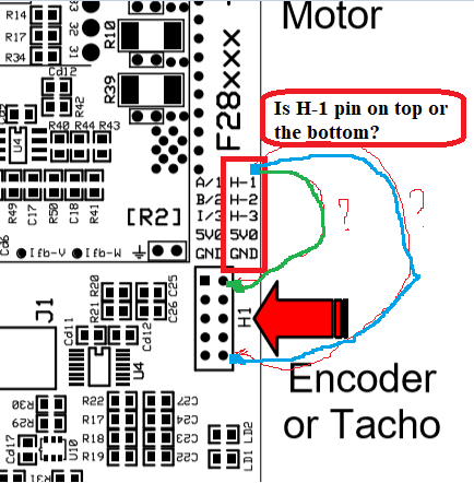
(So is H1-pin referring to green one (top) or blue one (bottom one)?) I have 5-pin out encoder and I believe it is where the encoder pin goes.
Also the schematics is as follows: I just wanted to conform if six-phase inverter outputs an 3-phase AC not an DC (I am not doubting documentation or something but just wanted to conform)

Oh by the way thank you everyone and forgive me if you believe this a very basic question. This lively community makes it possible for newcomers to test such amazing hardware.
