This thread has been locked.

If you have a related question, please click the "Ask a related question" button in the top right corner. The newly created question will be automatically linked to this question.

CCS/TMS320F28377D: Operation of "Delta-Sigma" module

Part Number: TMS320F28377D

Tool/software: Code Composer Studio

Hello
I want to use delta-sigma module to read the current in a PMSM drive. I am using TMS28F377D with AMC1305 delta-sigma modulator.
I am not expert and I am confused a little with the TRM section of delta-sigma!
I want to measure the current exactly in the beginning of my sampling period (Ts=50us). As I noticed, by using S-D module, an average value of current is achieved. The period of average is defined by "Latency of Sinc filter" (correct me if I am wrong).
Is it possible to reduce this period to about 1us? How should I adjust the SINC order and OSR for this purpose?

Other point is that as I have understand, there is duration in

which wrong data is sent by AMC1305 (tISTART in datasheet of AMC) and read by DSP (table 12-4 in TRM). Are this wrong data repeated in every time (every sampling time) I read the current from AMC ? if "yes", I think this may limit my minimum "Latency of Sinc filter". Is it true?

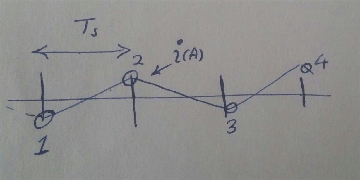
Please guide me how could I read the current in the beginning of every sampling time (Ts=50us) and only in a maximum duration of 1us . In fact I want to measure the current in the numbered time instances of the attached figure to estimate the torque of the motor and control it in a predictive manner.

regards

  • Hi Sana,

    It is possible to meet this 1us requirement, however you give up resolution for speed. The resolution required is application dependent.

    The AMC1305 seems to have a MAX frequency of 20MHz. Looking at the equations in section 12.5.2, your Modulator Data Rate would then be 20MHz, assuming you utilize this MAX. Let's say you then are using Mode 1 (which I think you have to at this frequency from the datasheet) and SINC1. We now just need to know what OSR to set.

    Latency of Sinc Filter = 1us = (Sinc#) / (Sinc filter data rate) = 1 / (20MHz / OSR) ==> OSR = 20

    The filter resolution is dependent on the SINC filter type (1, 2, 3, etc.) and the OSR (higher is better resolution).

    Regarding your 2nd question, I think the paragraphs under table 12-4 answer this quite well:

    SDFM Comparator interrupts (IELx and IEHx) should be enabled only after providing sufficient settling
    time to make sure the comparator filter does not trip on these incorrect samples. Therefore, SDFM
    comparator interrupts (IELx and IEHx) should be enabled only after a sufficient delay is provided after the
    comparator filter is configured. This sufficient delay is calculated by adding the latency of the comparator
    filter and five SD-Cx clock cycles.

    In case of the SDFM data filter, each time the filter is enabled or reconfigured, or the filter is reset by the
    PWM sync pulse, or the filter is reset by SDDFPARMx.FEN, depending upon the filter type, there will be
    some incorrect samples as mentioned in Table 12-4.

    Best,
    Kevin
  • Sana,

    What is the resolution / latency trade off your project demands? Resolution of SDFM depends upon SD-modulator frequency, OSR settings and filter type. Usually all the SD-modulator datasheet provide a plot between OSR vs settling time. This plot would be good starting point to decide the OSR settings and filter type.

    AMC1305 SD-modulator doesn't send any wrong data. When SDFM receives PWM synchronization pulse (SDSYNC), it resets the counter and it takes few samples to reach steady state (correct filter output). Number of incorrect samples depending upon the filter type (this is not a bug, it because of inherent nature sinc filter architecture).

    Regards,
    Manoj

  • Hello Kevin
    Thanks for your reply

    About the first question; how should I decide on OSR and SINC values? and if I adjust these values for 1us, does the module provides me every 1us the measured current during 1us (after the calculations of the filter is completed in the period of latency of filter) or it is continuously provide the data which is the moving average of the last 1us data?
    Should I enable PWM 11 and 12 for sync purpose to have the measured current exactly in the beginning of the control periods (points 1 ,2 ,3 .. in my attached figure)

    Regars
  • Dear Manoj

    I am not expert in digital filter subjects.
    I want to read the current of the motor in the points 1 , 2, 3 ,.. in the attached figure to control the motor. the other current data (for example in the middle of the control period ) is not important for me. I want the current value exactly in that points mentioned in the figure.
    I don't know reducing the "Latency of Sinc filter" to 1us is the correct way for my purpose and how does this reduction will degrade the current values which SDFM outputs to my control loop.

    regards
  • Hello again
    I have have done a little research about the sigma-delta module and sinc filter.
    As I have noticed, using the AMC and SDFM, only the AVERAGE current during a control period could be measured and NOT current at any exact instance (or at least a little period which is a little fraction of the control period ). I have read this in an online document:

    "From a control point of view the ADC can be seen as ideal—a conversion rate of typically 10 MHz to 20 MHz introduces insignificant delay in a control loop with a bandwidth of a few kHz. The sinc3 filter, however, introduces a delay and makes it impossible to talk about one defined sampling instant."

    Is it really true?! So no way to use this product for motor drive application which need sampling the current in exact instances such as model predictive control?

    please help me on this issue.

    regards
  • Sana,

    If you want to precisely time when you want to read SDFM filter results then you need to use PWM sync feature (SDSYNC). However, it is true that when you use SDFM sync feature, it is going to reset the SDFM data filter and then you have wait for latency of Sinc filter before you get a valid SDFM data filter output. There is no way around this.

    So, essentially when using PWM sync feature it is latency of sinc filter which needs to be accounted. If your system requires you read SDFM data filter around 1us. Then SDFM datafilter effective resolution (ENOB) would be very low around 4-6 bits depending on filter type. You can find this information in Pg27 of www.ti.com/.../amc1305l25.pdf

    Regards,
    Manoj