This thread has been locked.

If you have a related question, please click the "Ask a related question" button in the top right corner. The newly created question will be automatically linked to this question.

TMS320F28335: Unable to connect using CAN communication to F28335 experimenter kit

Part Number: TMS320F28335

Hi,

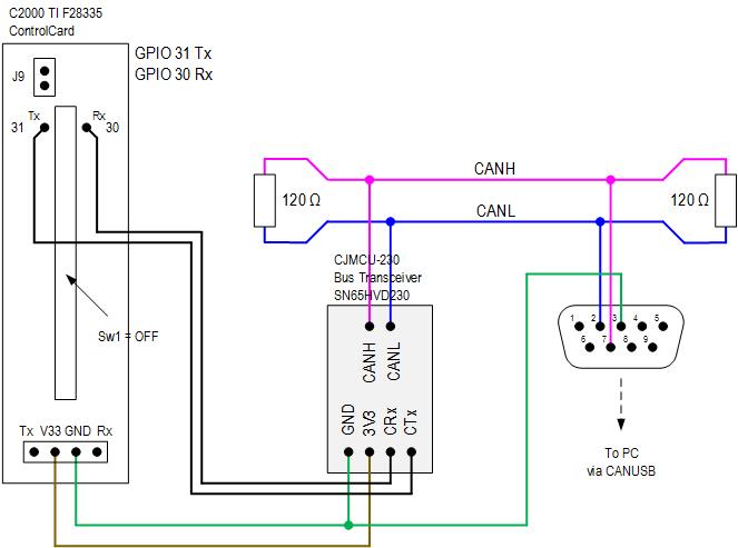
I am having trouble connecting to F28335 experimenter kit using CAN communication. I am trying to run this Simulink example. I get the message "External Mode Open Protocol Init command failed". I closed SW1 and opened J9 on the board.

I got everything needed for CAN communication from gathered from this post: CAN to USB converter and CAN transceiver. However, after reading CAN converter instructions I think I got the wrong one as it says:

"Also note that in order for CAN to work, you need at least 2 CAN nodes in operational mode (CAN specifications), the CAN network should also be properly teminated in both ends, so if you connect CANUSB in the end of the network, you must add one 120ohm resistor near the CANUSB and then one 120ohm resistor in the other end of the network."

I don't have 2 CAN nodes to start with.

On top of that I am not sure if the communication problem is due to converter, transceiver or software issue?! So many things to troubleshoot. Can you please confirm that I got the right products or recommend the proven and tested ones. Is there a local support (UK)? I might be missing just one small thing in my communication chain and if somebody looks at my set-up it may save time and nerves.

I want to trying CAN communication as it is more robust than serial and I have problems with serial and noise.

Kind regards.

  • Hi Mike,

    A quick question, as the above experimenter kit doesn't have a CAN transceiver - did you add one? This component is a must for successful CAN communication - even with CAN to USB converter.

    Regards,
    Gautam
  • Hi Mike,

    Did you get this resolved.

    You need to create a CAN BUS and there are CAN Transceivers that should be connected. The 120 ohm register is for creating CAN Bus.

    Let me know if you still have any doubts.

    Thanks and Regards
    Harshmeet
  • Hi Harshmeet,

    I have CAN Transceiver and added 120 Ohms on each end of the bus. But still, I cannot connect. I always get the message: Unable to connect to the 'TI Delfino F2833x' target for 'c28x_ccp_ert'.

    I even connected to GIPO 30 (Rx) and 31 (Tx) for eCAN_A instead of J3 Tx and Rx pins. I tried with Sw1 on DSP board in on and off position and still no connection. J9 is disconnected all the time. 

    is there any local support that can take a look at this issue or provide consulting services. I have been working on and off on this for a while, I cannot postpone it anymore. I really don't know what to do next. It can be hw or sw problem or even Matlab. I don't mind buying new and different Transceivers and CAN to USB converter (which one?) but I am not sure this if will solve all the problems.

    I cannot change control card as all hardware is already built around it and serial communication is giving me problems.

  • Reading your post, I am confused if you have a CAN communication issue or a CCS connectivity issue. Are you able to connect to your target using CCS and load/run/debug code? If not, that issue needs to be resolved first.


    Regarding CAN, have you read section 3 (Debug and Design Tips to Resolve/Avoid CAN Communication Issues) of my app.note SPRA876? If not, please do so.


    Can you send the wiring diagram of your CAN bus that shows all the critical components? Hand-drawn is OK.

  • Hello Hareesh,

    please see wirring diagram:

    I have only one node. I will try in self-test mode to see if this solves the problem.

    With serial communcation I am able to comucante with CCS and load/run/debug code.

    Kind regards,

    Igor

  • Igor,
    You have not answered my question about referring to my app.note. The examples were written/tested on 28335. All you need to do is to run the transmit example CAN_TXLOOP_A.

    Also, it appears CJMCU-230 board already has a 120-ohm terminator. I notice you have one more terminator close to the board externally.
  • Hello Hareesh,

    I appreciate all the help you and your colleagues have provided so far. This is my first encounter with CCS, coding and CAN communication. I tried to run example you proposed  from CCS but I could not get it to work. Maybe part of it is due to my elementary knowledge of CCS and coding. That is the reason I am using Simulink. I tried also with different transceiver, but still not success. I ordered a new CAN to USB converter, maybe this will help. I assume for troubleshooting a certain level of knowledge is good to have, which I don't have. 

    Hence I keep asking for a personal form of help. Are there any TI centers or companies that know how to make this TMS320F28335 card work for CAN bus in the UK or Europe? In this chain there are 100 things that can go wrong and I am really in need of a consultation, support and guidance. Please advise.

    Kind regards

  • Igor,
    I agree there are many things that could wrong and certainly empathize with your predicament. You mention you are new to “CCS, coding and CAN communication”. This makes support over the forum a bit challenging. Do you have a TI FAE supporting your company?

    I have pointed to many useful resources in this post for beginners like you: (Please look at the very end of the thread) e2e.ti.com/.../745605
    I am afraid you have to put in the time/effort to learn the basics of CCS, C2000 architecture, running the app.note examples etc. Even assuming I am able to help out with the current problem, sooner or later it is likely you will be stuck again with a different problem. Hope you understand.

    If you have an oscilloscope, please probe the CANTX pin and let me know what you observe. And bear in mind that in network, there can only be two terminators and only at either ends of the bus. If we go step-by-step in a methodical manner, debugging this should be fairly straightforward.
  • Mike,

    Just saw this thread.

    1) Check that the Vector-Informatik CAN HW is installed correctly. Best I can tell, this example requires it.  Also, info on set-up which might be useful https://www.mathworks.com/help/supportpkg/texasinstrumentsc2000/ug/set-up-the-hardware-for-can-communication-between-the-target-and-the-host-computer-.html

    2) If there are no obvious issues with the CAN setup and the model still isn't building, you can try working exclusively in CCS; just to see if you can get CAN running on the board and talking to the vector SW. Check CCS for CAN examples you can load.

    3) If the HW is working, but the model deployment from Simulink is still not working, contact MathWorks Tech Support for assistance.  They can help with the MathWorks side, but they probably dont have access to HW (Vector CAN HW or TI board).

    Cheers,

    -Brian

  • Hi Brian,

    thank you for the reply. Does this mean I have to get a hardware from Vector? I just ordered another CAN to UBS adapter (300 EUR). And the one I am using (100 GBP) did not come with apps like btest32.exe and vcanconf.exe. I am now looking at Vector's VN1610. Is this okay? I think this is a CAN USB adapter.

    Simulink model is building successfully. It is just deploying to hardware that doesn't work. So problem can be in hardware (connection, pins, etc.) or software (drivers, setup, etc.). 

    Hence, I would really benefit from comparing my setups against the working one so I can start replacing bit by bit, thus identifying not working area.  Are there any companies using TI and CAN and Simulink and willing to consult on this? At the moment I am just guessing and losing time (and money) perusing every angle. Unfortunately, this is my side project and since I work in a different area and different tools, so any company's support is non existing.

    Kind regards

  • Hi Mike,

    I'm not 100% certain; it looks like the example is set up to run with a specific set of HW, but I don't know if it is strictly *required*.

    One way to debug is to use CCS and download an example there. If that works, then you know the HW is good and it is a MathWorks issue.  if that doesn't work, you know it is a HW issue you need to debug before trying to get the MathWorks implementation working.

    For faster assistance, you can contact MathWorks Technical Support; they can log the issue, review it against our database of customer issues and fixes, and/or escalate to the development team as needed.

    Cheers,

    -Brian