This thread has been locked.

If you have a related question, please click the "Ask a related question" button in the top right corner. The newly created question will be automatically linked to this question.

TMS320F28335: ADC GROUND

Part Number: TMS320F28335
Other Parts Discussed in Thread: C2000WARE

1. I am using TMS320F28335 Experimenter Kit with matlab.I just want to read the ADC value.To use ADC do I need to connect any external components?(like capacitor)

2. Where is ADCLO located in experimenter kit?

  • karthika s said:
    1. I am using TMS320F28335 Experimenter Kit with matlab.I just want to read the ADC value.To use ADC do I need to connect any external components?(like capacitor)

    The F28335 controlCARDs is designed for the ADC to work with internal reference mode without additional external components.

    karthika s said:
    2. Where is ADCLO located in experimenter kit?

    ADCLO is connected to the board ground.  You can find the schematics in C2000Ware if you require them.

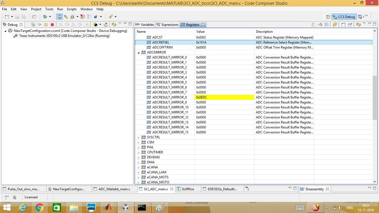
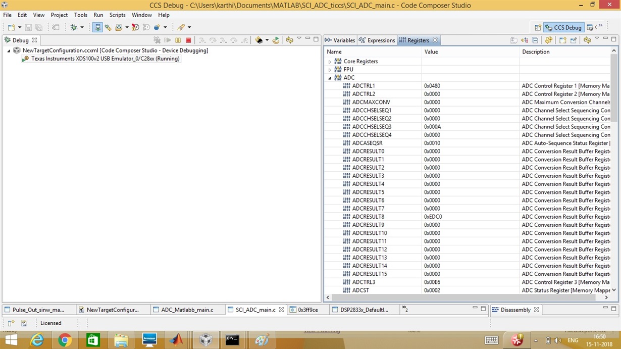
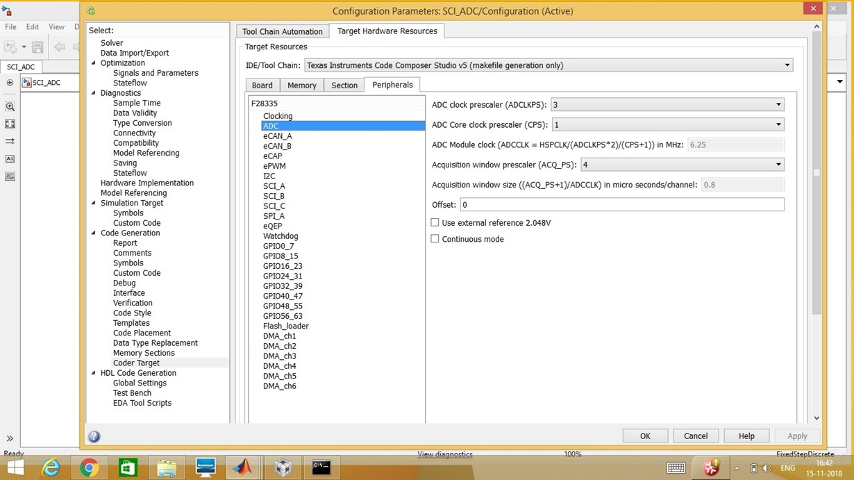
  • Thank you a lot for your quick response.Here I am trying to read ADC value from MATLAB through CCS.Given input voltage is 1.3V but the results shown in ADCRESULT Register is Hexa decimal EDC value.It shows some error result.Kindly help me with this.Thank you

  • karthika,

    On which pin are you forcing the voltage?  And what is the nature of the voltage source that you are trying to convert?  Are you able to verify the source signal using an oscilloscope during the ADC conversion?

    -Tommy

  • Thank you Tommy...

    1. I am forcing the voltage in ADCB2 pin

    2. Nature of voltage:DC supply 1.3V

    3. Yes I am able to verify the source signal using oscilloscope during the ADC conversion
  • karthika,

    Can you also measure the voltage across capacitor C19, which is connected to ADCINB2?  I assume that your DC supply is sharing a ground reference with one of the GND pins on the docking station.

    Are you using a true DC bench supply with low impedance or is it a function generator that is possibly configured for 50Ω termination?

    Do any other ADC channels work?  Is this a new kit?  Has the ADC ever worked before?

    -Tommy

  • Tommy,

    Thank you for your time.

    1. Can you also measure the voltage across capacitor C19, which is connected to ADCINB2? 

    I didn't connect anything externally.If its present in TI Experimenter Kit,I will measure it.

    2. I assume that your DC supply is sharing a ground reference with one of the GND pins on the docking station.

    Yes

    3.Are you using a true DC bench supply with low impedance or is it a function generator that is possibly configured for 50Ω termination?

    Yes.Regulated Power Supply

    4.Do any other ADC channels work? 

    No.Every channel gives the same error.

    5.Is this a new kit? 

    No

    6. Has the ADC ever worked before?

    Couldn't get that information from college.


  • karthika s said:

    1. Can you also measure the voltage across capacitor C19, which is connected to ADCINB2? 

    I didn't connect anything externally.If its present in TI Experimenter Kit,I will measure it.

    C19 is a capacitor that is populated on the controlCARD.

    karthika s said:

    4.Do any other ADC channels work? 

    No.Every channel gives the same error.

    5.Is this a new kit? 

    No

    6. Has the ADC ever worked before?

    Couldn't get that information from college.

    Which revision controlCARD do you have?  For example, R2.2 is the latest one.  Is there a way for you to find another kit for comparison?

  • karthika,

    It has been a while since your last update. I assume that you were able to resolve your issue. If this isn’t the case, please reject this resolution and reply to this thread. If this thread is locked, please make a new thread describing the current status of your issue.

    -Tommy