


Other Parts Discussed in Thread: CONTROLSUITE
Dear Ramesh,
Thank you for your review.
I need to discuss more on the update rate of the DACVALA register with you.
Even though you confirmed that the DACVALA register should be updated at every 100us according to the associated register settings, it is not updated at every 100us as follows.
It is stated in the file of resolver.c as follows:
----------------------------------------------------------------------------------------------------------------------------------------------------
interrupt void ResolverISR ( void )
{
// *** Set up next sampling instant and update excitation sine wave ***
rslvrOut.sineIndex = (rslvrOut.sineIndex-1) & (rslvrIn.TABLE_LENGTH-1); // DELAY_LENGTH must be 2^n
DacaRegs.DACVALS.bit.DACVALS = sineTable[rslvrOut.sineIndex];;
-----------------------------------------------------------------------------------------------------------------------------------------------------
The interrupt service routine ResolverISR() is executed at every 6.25us.
I measured the resolver carrier signal on the IDDK main board.
Its shape is a 10 kHz sine wave as shown in the captured display inserted below.
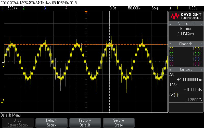
The captured display inserted below shows one period of the 10 kHz carrier signal.
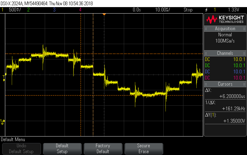
The carrier signal is updated 16 times in one period of 100us.
Therefore the carrier signal is updated at every 6.25us; it is updated at every execution of ResolverISR().
Please review this issue for me.
Thank you for your guidance.
G. Kim
