This thread has been locked.

If you have a related question, please click the "Ask a related question" button in the top right corner. The newly created question will be automatically linked to this question.

LAUNCHXL-F28027F: How to configure motorware user.h parameters for BOOSTXL-DRV8304H

Part Number: LAUNCHXL-F28027F
Other Parts Discussed in Thread: MOTORWARE, DRV8304, BOOSTXL-DRV8301, DRV8301, LAUNCHXL-F28069M, BOOSTXL-DRV8304H, TMS320F28027F

I've tested LAUNCHXL-F28027F + BOOSTXL-DRV8301 bundle and now working on reconfiguring motorware user.h for DRV8304. 

I recalculated the parameters according to  

guide. I changed USER_ADC_FULL_SCALE_VOLTAGE_V, USER_ADC_FULL_SCALE_CURRENT_A  and USER_VOLTAGE_FILTER_POLE_Hz.

// (ADC_IN_MAX*R1 + R2)/R2 = (3.3*82 + 7.5)/7.5 = 37.08 // for boostxl-drv8304, R7, R8,R9 = 82K, R3,R4,R5 = 7.5K

#define USER_ADC_FULL_SCALE_VOLTAGE_V (37.08) // 26.314 boostxldrv8301_revB voltage scaling

/#define USER_ADC_FULL_SCALE_CURRENT_A (47.1) // 33.0 boostxldrv8301_revB current scaling

// For drv8304 kit
// Rp = (R2*R1)/(R1+R2) = (82*7.5)/(82+7.5) = 6.87
// C = 0.1 uF -  C2, C3, C4 were not soldered on the stock kit, so added them manually
// 1/(2*pi*R*C) = 1/(2*pi*6870*0.0000001) = 231.784
#define USER_VOLTAGE_FILTER_POLE_Hz (231.784) // 364.682, value for boostxldrv8301_revB hardware

But the motor behaves badly - shakes and pulls big current. 

USER_ADC_FULL_SCALE_VOLTAGE_V seems calculated correctly, because measured Vdc is correct.

But how to calculate USER_ADC_FULL_SCALE_CURRENT_A? I set it to 33*0.01/0.007 = 47.1, because DRV8301 kit has 0.01 shunts and DRV8304 one has 0.007 shunts, so I just changed USER_ADC_FULL_SCALE_CURRENT_A proporitonally.

The instaspin guide offers a formula in  the chapter 5.2.1, that uses opamp resistors values, but I didn't find what resistors values opamps integrated into DRV8304 have.

GAIN is default - 10V/V (tied to GND through 47k)

MODE is 6x PWM - tied to GND

The only modification I made to the DRV8304 kit was soldering 0.1 uF capacitors for voltage sensing. 
May be I missed something else.

  • I am looking into the details of the DRV8304 Booster Pack to get a better answer for you. In the mean time, did you change any of the HAL drivers for the DRV8304 from the DRV8301 implementation? I'm assuming that you haven't changed the gain setting from the default value of 10 during DRV initialization?

    Sean
  • Hello Sean! Correct, I haven't changed GAIN, nor any other parameter from default value. I use ony hardware interface and do not use SPI at all. And didn't modify HAL for DRV8304.
    UPD:
    Managed to run open-loop mode (lab 1b). Runs good, measured oscillograms of opamps outputs - voltage feedback was trapezoidal and current sinusoidal. But when enabled closed loop mode (lab 1c) rotor would stall and current go high. Tried 40V/V and 5 V/V opamps gain (pulled gain to Vdd or GND).

    Experiencing a lack of debug tooling for TMS320F28027F, going to switch to LAUNCHXL-F28069M and use DAC, datalog. Put LAUNCHXL-F28069M+BOOSTXL-DRV8301 and LAUNCHXL-F28069M+BOOSTXL-DRV8304H side by side and compare outputs.

    Have no idea, why that happens. BOOSTXL-DRV8304H may not be mounted to Instaspin kits directly, so connected DRV8304 kit by wires reproducing DRV8301 connection. The code left intact, except Voltage/Current scaling coefficients. 

    Sean, may there be some major difference between BOOSTXL-DRV8304H and BOOSTXL-DRV8301? May be DRV8304 current or voltage feedback have different polarity (scaling calculation formula, bias offset estimation) of DRV8301 or something. There is not much code samples for DRV8304, only one project for trapezoidal commutation. That one doesn't use current feedback as far as I understood. 

  • I've calculated the USER_ADC_FULL_SCALE_VOLTAGE_V as 39.38, which does not match with your calculation. Can you try to change this value and retry. The small discrepancy should not cause such a large issue though. Which lab are you using that shows such an issue? Have you tried to identify the motor in lab2b? It appears that the polarity of the current sense op-amp is also inverted when compared to the DRV8301. You will most likely need to change the sign of the current in HAL_readAdcData(). You may add a '-' to the current_sf variable to accomplish this

    Sean

  • >>>Which lab are you using 

    Initially it was a highly customized project based on lab 05b that works good with DRV8301. But to exclude side effects of custom code currently experimenting with lab 01b (open loop) and trying to bring up lab 01c. With DRV8301 lab 1c works good, with DRV8304 doesn't.

    >>>Have you tried to identify the motor in lab2b

    I identified motor with DRV8301 before.

    You are right, I made a mistake: (ADC_IN_MAX*R1 + R2)/R2 should be ADC_IN_MAX*(R1 + R2)/R2. Thank you for the clue, I'll try it and post results here.

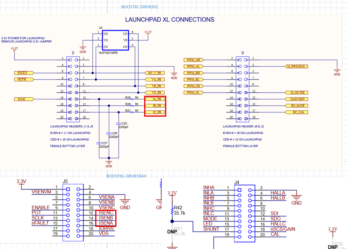
  • Finally got it working. Found out, the polarity was correct - no need in inversing. Phases current feedback A and C were confused. That was because of manual wiring and a bit confucing header mapping. If it is VA,VB,VC,IA,IB,IC for DRV8301 kit, it is VA,VB,VC,IC,IB,IA for DRV8304 kit. 

    So, resuming the changes replacing DRV8301 kit vs DRV8304:


    #define USER_ADC_FULL_SCALE_VOLTAGE_V 39.38

    #define USER_ADC_FULL_SCALE_CURRENT_A 47.142857 //Vref/(Rs*GAIN) = 3.3/(0.007*10) 

    Thank you for support Sean!