This thread has been locked.

If you have a related question, please click the "Ask a related question" button in the top right corner. The newly created question will be automatically linked to this question.

TMS320F28377D: 28377d chip in flash mode, programming code to CPU2 is not normal

Part Number: TMS320F28377D
Other Parts Discussed in Thread: C2000WARE, TPS3808

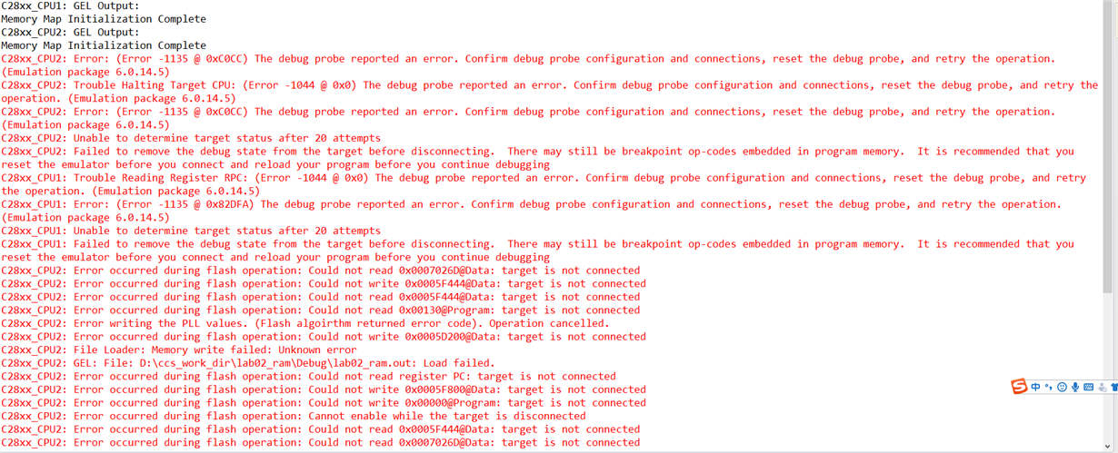
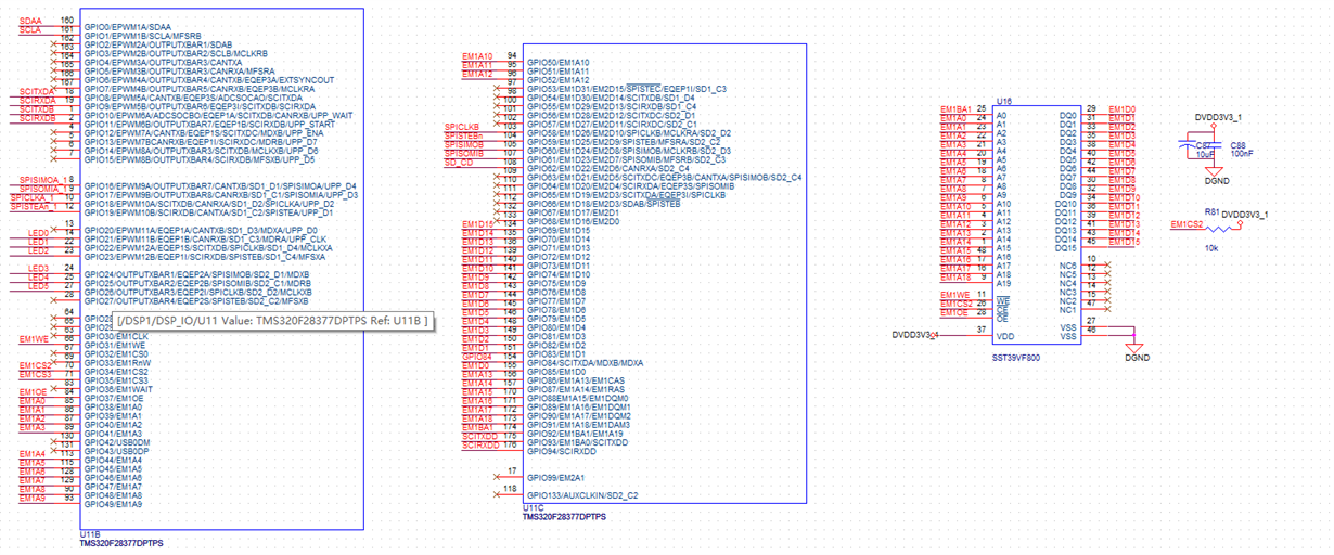
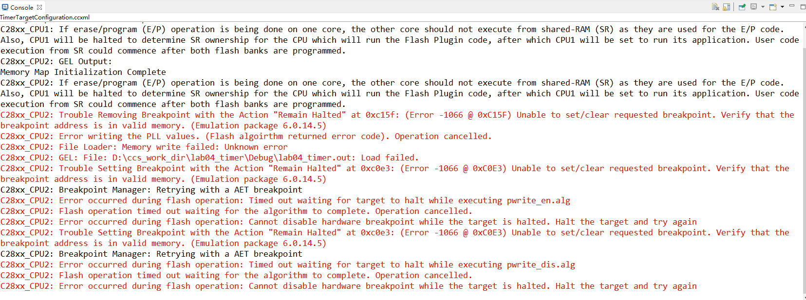
hello, I have designed a new board using 28377d, but in ram mode ,the two cpu load program succeed,while in flash mode ,only cpu1 load program is ok,load program to cpu2 has some errors.The error is as follows:and my Schematic is also attached below:

  • Hi,

    What are you using to load code into the device?

    sal
  • hi,thanks for your reply.I am using the YXDSP-XDS200 emulator.and in flash mode,when I want to load code into cpu2 after my code have been loaded into cpu1 ,errors occurred.
  • Are you using CCS to load the code? You typically need to load two distinct .outs, one for each CPU.

    sal
  • 28377核心板原理图.pdfthanks for your reply.I did use ccs to load my code.

    But one project can only generate one .out, and I have another development board, also used 28377d chip, can download the same .out file to two CPUs, I upload the schematic, can you help me compare to myselves'  schematic to confirm whether my design have some wrong?

  • I am not the right person to look at this. Let me request some help from another engineer.

    sal
  • Hi Tianyi,

    Based on the error messages provided it seems like a JTAG or connection issue while programming. When you are attempting to program the device do you only have your XDS-200 emulator connected? I see on the schematic you have JTAG signals (TXK, TDO, TDI, TMS) routed to header J3. I want to make sure you have nothing else connected to these signals that could be disrupting these signals.

    You say you have tried running your program on CPU2 from RAM and that works? Could you try running one of the Dual CPU examples from c2000ware just to be sure. Try running (programming AND executing) an example on CPU2 from RAM and then FLASH. You could try the one at the directory below:

    C:\ti\c2000\C2000Ware_1_00_06_00\device_support\f2837xd\examples\dual\ipc_gpio_toggle\cpu02

    Best,
    Kevin
  • thanks for your reply,

    I sure that my device only connect to XDS-200emulator,and nothing else signal connected to my JTAG  pin,I will upload my schematic for JTAG.

    I have run program on cpu2 in ram mode and it did work.follow your suggestion,I run the project ipc_gpio_toggle\cpu02 first from ram ,and two cpu works.but when I try to run on flash ,same errors occurs.Beside, I try to running only on cpu2 ,also have errors,and experences shows that I must run on cpu1 before load program to cpu2. I will list the error.

    best wishes. dsp_config.pdf

  • Hi Tianyi,

    Can you please try what's suggested in this prior E2E post:

    https://e2e.ti.com/support/microcontrollers/c2000/f/171/t/397002

    Can you try the below steps? I just removed the step in which you load code in to CPU1. I want to make sure that CPU1 is not disconnected. Screenshots that you sent earlier show that you are disconnecting CPU1.

    1) Launch the target configuration from the Target configurations window (View -> Target Configurations -> Right click on the F28377D ccxml -> Launch selected configuration)

    2) Connect to CPU1 and then to CPU2 (In the debug window, select the C28xx_CPU1, right click -> Connect Target. Do the same thing for C28xx_CPU2).

    3) Reset CPU1 and then CPU2 (Select C28xx_CPU1, then in the debug window menu -> Run -> Reset -> CPU reset. Do this for C28xx_CPU2)

    4) Load the code in CPU2 (Select C28xx_CPU2 and then in the debug window menu click on "Run" -> Load -> Load program and choose the .out file that you want to load in to CPU2)


    Best,

    Kevin

  • thanks for your suggestion,
    I have follow your guide step on step, but same errors as I upload first occurs. And I have a development board which schematic has uploaded as "28377核心板原理图.pdf" ,the same operation on it lead to no errors. So I doubt that whether my design for Hardware circuit has some illegal details, but I can load program to cpu1 shows that my circuit might be correct.
    Do you think it is possible that my illegal design for schematic lead to these errors?

    Best,
    Tianyi.
  • Hi Tianyi,

    I am a little confused, you have multiple boards? You're saying the board you have that matches up with "28377核心板原理图.pdf" works as intended when loading both cpu1 and 2? But another board you have does not?

    You're certain that CPU1 is connected when trying to program CPU2? Maybe try the same steps above but without resetting the cores. Also make sure CPU1 is halted and not running when programming CPU2.

    Further details can be found in the post linked below:

    e2e.ti.com/.../553977

    Best,
    Kevin
  • hi Tianyi,

    I don't notice anything particularly wrong with your JTAG schematic. Maybe placing a 0 ohm resistor on R65 instead of 100 ohm could help. That's the only thing I can think of when comparing your schematic to our reference ones.

    Best,

    Kevin

  • Hi Tianyi,

    Were you able to resolve this issue? If so I'm going to go ahead and close this thread.

    Best,
    Kevin
  • OK,thanks,
    I have replaced R65 with 0 ohm, but it did not have any help.

    thanks and best
  • DSP.pdf4722.dsp_config.pdfHi Kevin,

    I did have two boards, the board matches up with  "28377核心板原理图.pdf" is I buy from others, and it did work normolly when loading both cpu1 and cpu2(not only follow your steps works,but also use  the "debug" button works), the board has errors  intended was I imitated it .

    And I really make sure when I programming cpu2, cpu1 was connected and halted.

    I will upload my whole 28377d part, the two .pdf as follows, can you help me to check what lead to this problem? And I found that the WE pin int my 28377d chip is not connected to flash, do you think this may has some influence?(while I can load program to cpu1 in flash mode,this is why?) 

    thanks and best,

    Tianyi

  • Tianyi,

    I'm not understanding. You have an evaluation board that you bought that does work, but your own custom board is not working? Have you identified the differences between the boards if so?

    You're talking about the External Memory Interface (EMIF) WE pin? You're using an external flash then? If you're trying to load this external flash it's important to get this connection correct (WE) included.

    Best,

    Kevin

  • Hi Kevin,
    it is as your understanding, my own board can not programming the cpu2 in flash mode while the bought one can do it even in the same operation.
    And e External Memory Interface (EMIF) WE pin not connected to my 28377d, as the "dsp_io.dsp" that will be upload, I do not understand this not connect caused some error or not, why I can load program to cpu1 in this condition.
  • Hi Tianyi,

    After discussing some with my colleague, it would be unusual to load your program to this external flash which is interfaced using the device's EMIF. The GPIOs used are not configured for EMIF initially so it seems highly unlikely that this external flash connection is the root problem.

    Could you check the boot mode (see boot mode pins) being used on your custom board versus the working evaluation board you have? Please try this procedure with a boot mode other than Get-Mode (which boots from flash) and see if that works.

    Best,
    Kevin
  • Hi Kevin,

    Do you mean that when choose flash mode or ram mode, what we operate is only 28377d(it contains flash and ram),and it is less related to external flash? If so, what role the external flash and sdram play?

    In addition, I don't know how to check boot mode, can you give me an example?

    best,
    Tianyi
  • Tianyi,

    When you're programming to flash you are writing to the internal f28377d flash not the external flash or sdram. The external sdram and flash in your schematic are being interfaced to using the f28377d's EMIF (External Memory Interface) peripheral, which isn't initialized before programming. The external flash and sdram could be written to within your application, but that shouldn't be where your f28377d's program is being stored.

    If you check the addresses in your linker command file you can see where your program is getting stored in memory. They should be device memory addresses.

    The boot mode is set based on the state of some pins. Please see the table below and try boot modes other than "Get Mode":

    Best,

    Kevin

  • Hi Kevin,

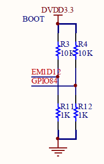
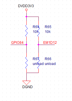
    you mean that I should set the gpio72 and gpio84 as not connect to any pin? And what is TRST pin? I don't find it.

    The working evaluation board set the mode as above,EM1D12 is gpio72. And my own board is also set as it but has the error.

    Bset,

    Tianyi

  • What's more, my mode set as follow, it might be get mode. And nearly I found that after I load program to cpu1, I must run it and then suspend, after two operation, program can be load to cpu2. If I load program to cpu1 not run and suspend(I mean in this time, my cpu1 is also suspend),  then program cpu2 errors as  above occurs.

  • Tianyi,

    TRST is a pin on the device. Please check the datasheet to find which pin.

    You should pull up/down these pins for the respective boot modes.

    Best,
    Kevin
  • Hi Kevin,

    I have checked that my TRST is low, so the mode is EMU boot mode. By reason, no matter what my gpio84 and gpio72 is low or high, it cause nothing.But I found that when my gpio84 and 72 is high, I must program cpu1 first , then run it and suspend, and I can program cpu2, if not run,program cpu2 causes errors as mented above.While when the gpio84 and 72 is low, with the same operation with it is high, ccs point that maybe in low power mode.

    I want to know what caused that I must run program in cpu1 and suspend it before I program cpu2? and both in EMU boot mode, why gpio84 and 72 is low caused low power mode?

    Best,
    tianyi

  • Tianyi,

    If TRST is low then you are not using emulation (EMU) boot mode. EMU boot is the only option that requires TRST to be high.

    The mode you described with TRST low, and GPIO 72 & 84 high is Get Mode, which defaults to running from flash if not altered. This is not the desired boot mode if debugging or programming.

    Best,
    Kevin
  • Kevin,
    I have set TRSTn high, in EMU boot mode, but errors as mented occurs.
    What's more ,while in get mode, I must program cpu1 first , then run it and suspend, and I can program cpu2, if not run,program cpu2 causes errors as mented above. what caused this phenomenon?

    thanks and best
    tianyi
  • Tianyi,

    CPU1 should be halted/suspended before programming CPU2, that is the correct behavior.

    I'm confused how you are programming when using GetMode. You should not be able to connect to the device at all in this mode, unless you maybe altered the OTP configuration for GetMode, but even then I still don't think you can connect.

    Looking at the "Dual-Core Inter-Processor Communications" section of the multi-day workshop may help you better understand dual core programming.

    Multi-day F28379D Workshop:

    Workshop Guide:
    http://software-dl.ti.com/trainingTTO/trainingTTO_public_sw/c28x28379/F2837xD_Microcontroller_MDW_2-0.pdf

    Best,

    Kevin

  • Kevin,

    I mean that I must run program on cpu1 and then halt, not only be suspend(affter load program to cpu1 successfully, it is suspend , but in this status, load program to cpu2 has errors as I have mented). And my demo board is also in get mode.

    What's more, I have not connect to restart chip "tps3808", after connect to it , even the before success  also has errors, and the error is halt-related error as below.

    best,

    tianyi

  • Hi Tianyi,

    Could you verify that your target configuration is for F28377D and not some other device:

    Also might be good to check if you can successfully erase the flash in CCS. To do this launch your target configuration and connect to your device. On the toolbar at the top select "Tools" and then "On-Chip Flash". Scroll down to Erase Settings and erase the entire flash. See if this is successful.

    Best,

    Kevin