


Other Parts Discussed in Thread: MOTORWARE
Tool/software: Code Composer Studio
Hello, I am currently designing a control system for a custom made blood pump motor which is a BLDC motor in an impeller chamber with an inlet and outlet for water. The parameters defined below through the use of lab2b. The poles were found using a magnet and the max voltage it can safely run is 15V and 1A current.
#elif (USER_MOTOR == My_Motor)
#define USER_MOTOR_TYPE MOTOR_Type_Pm
#define USER_MOTOR_NUM_POLE_PAIRS (2)
#define USER_MOTOR_Rr (NULL)
#define USER_MOTOR_Rs (5.66250801)
#define USER_MOTOR_Ls_d (0.00129274279)
#define USER_MOTOR_Ls_q (0.00129274279)
#define USER_MOTOR_RATED_FLUX (0.0127586192)
#define USER_MOTOR_MAGNETIZING_CURRENT (NULL)
#define USER_MOTOR_RES_EST_CURRENT (0.1)
#define USER_MOTOR_IND_EST_CURRENT (-0.1)
#define USER_MOTOR_MAX_CURRENT (1.0) //max rated current of motor
#define USER_MOTOR_FLUX_EST_FREQ_Hz (60.0)
The motor will perform well from 0 - 2000 rpm and then the motor starts shaking and making a loud mechanical noise. I have followed through the motorware user guide carefully from lab 1 to lab5b which I am using for the speed and current gains. They are as follows; (I have calculated Kp_Idq according to chapter 5 in motorware user guide and have also trial and error tested the speed gains to see if it would improve performance and they did not)

To improve the resolution of the current shunt amplification circuit, a 100mOHM shunt resistor was used on the f28027F board as this increased the ADC resolution due to the intial input current only being 1A. However this did not entirely fix the issue and only slightly improved performance.
I know this question is very vague and difficult to answer without having the motor to test but is there anything I am missing? Or is there something I should test. I was wondering if I should also increase the gains of the voltage sense circuits by 10 fold to compensate for the lower input voltage. Any help or recommendations would be extremely helpful, i'm desperate!
This is my user.h code,
//! \brief CURRENTS AND VOLTAGES
// **************************************************************************
//! \brief Defines the full scale frequency for IQ variable, Hz
//! \brief All frequencies are converted into (pu) based on the ratio to this value
//! \brief this value MUST be larger than the maximum speed that you are expecting from the motor
#define USER_IQ_FULL_SCALE_FREQ_Hz (480) // (800.0) //(200.0) // 800 Example with buffer for 8-pole 6 KRPM motor to be run to 10 KRPM with field weakening; Hz =(RPM * Poles) / 120
//! \brief Defines full scale value for the IQ30 variable of Voltage inside the system
//! \brief All voltages are converted into (pu) based on the ratio to this value
//! \brief WARNING: this value MUST meet the following condition: USER_IQ_FULL_SCALE_VOLTAGE_V > 0.5 * USER_MOTOR_MAX_CURRENT * USER_MOTOR_Ls_d * USER_VOLTAGE_FILTER_POLE_rps,
//! \brief WARNING: otherwise the value can saturate and roll-over, causing an inaccurate value
//! \brief WARNING: this value is OFTEN greater than the maximum measured ADC value, especially with high Bemf motors operating at higher than rated speeds
//! \brief WARNING: if you know the value of your Bemf constant, and you know you are operating at a multiple speed due to field weakening, be sure to set this value higher than the expected Bemf voltage
//! \brief It is recommended to start with a value ~3x greater than the USER_ADC_FULL_SCALE_VOLTAGE_V and increase to 4-5x if scenarios where a Bemf calculation may exceed these limits
//! \brief This value is also used to calculate the minimum flux value: USER_IQ_FULL_SCALE_VOLTAGE_V/USER_EST_FREQ_Hz/0.7
#define USER_IQ_FULL_SCALE_VOLTAGE_V (19.5)//(19.5)//(15.0) // 24.0 Example for boostxldrv8301_revB typical usage and the Anaheim motor
//! \brief Defines the maximum voltage at the input to the AD converter
//! \brief The value that will be represented by the maximum ADC input (3.3V) and conversion (0FFFh)
//! \brief Hardware dependent, this should be based on the voltage sensing and scaling to the ADC input
#define USER_ADC_FULL_SCALE_VOLTAGE_V (26.314) // 26.314 boostxldrv8301_revB voltage scaling // measurement receives 26.314V with a chip voltage of 3.3V
//! \brief Defines the voltage scale factor for the system
//! \brief Compile time calculation for scale factor (ratio) used throughout the system
#define USER_VOLTAGE_SF ((float_t)((USER_ADC_FULL_SCALE_VOLTAGE_V)/(USER_IQ_FULL_SCALE_VOLTAGE_V)))
//! \brief Defines the full scale current for the IQ variables, A
//! \brief All currents are converted into (pu) based on the ratio to this value
//! \brief WARNING: this value MUST be larger than the maximum current readings that you are expecting from the motor or the reading will roll over to 0, creating a control issue
#define USER_IQ_FULL_SCALE_CURRENT_A (1.3)// (1.3) // // // 20.0 Example for boostxldrv8301_revB typical usage
//! \brief Defines the maximum current at the AD converter
//! \brief The value that will be represented by the maximum ADC input (3.3V) and conversion (0FFFh)
//! \brief Hardware dependent, this should be based on the current sensing and scaling to the ADC input
#define USER_ADC_FULL_SCALE_CURRENT_A (1.65)// 33.0 // boostxldrv8301_revB current scaling
This is Phase voltage C at 2000 RPM
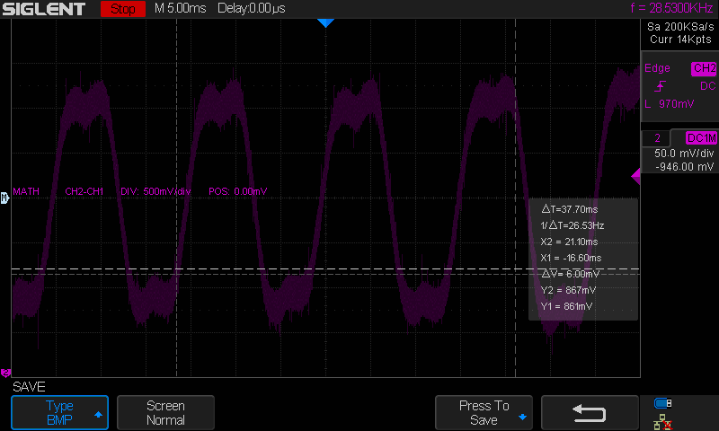
and at 4000 rpm (when the motor is noisy)


