This thread has been locked.

If you have a related question, please click the "Ask a related question" button in the top right corner. The newly created question will be automatically linked to this question.

F28M36H33B2: USB_UART Monitor

Part Number: F28M36H33B2
Other Parts Discussed in Thread: CONTROLSUITE, F28M36P53C2

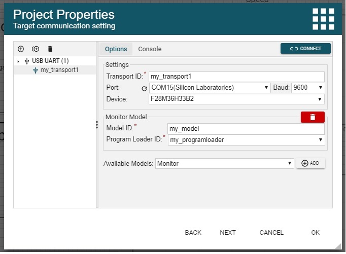
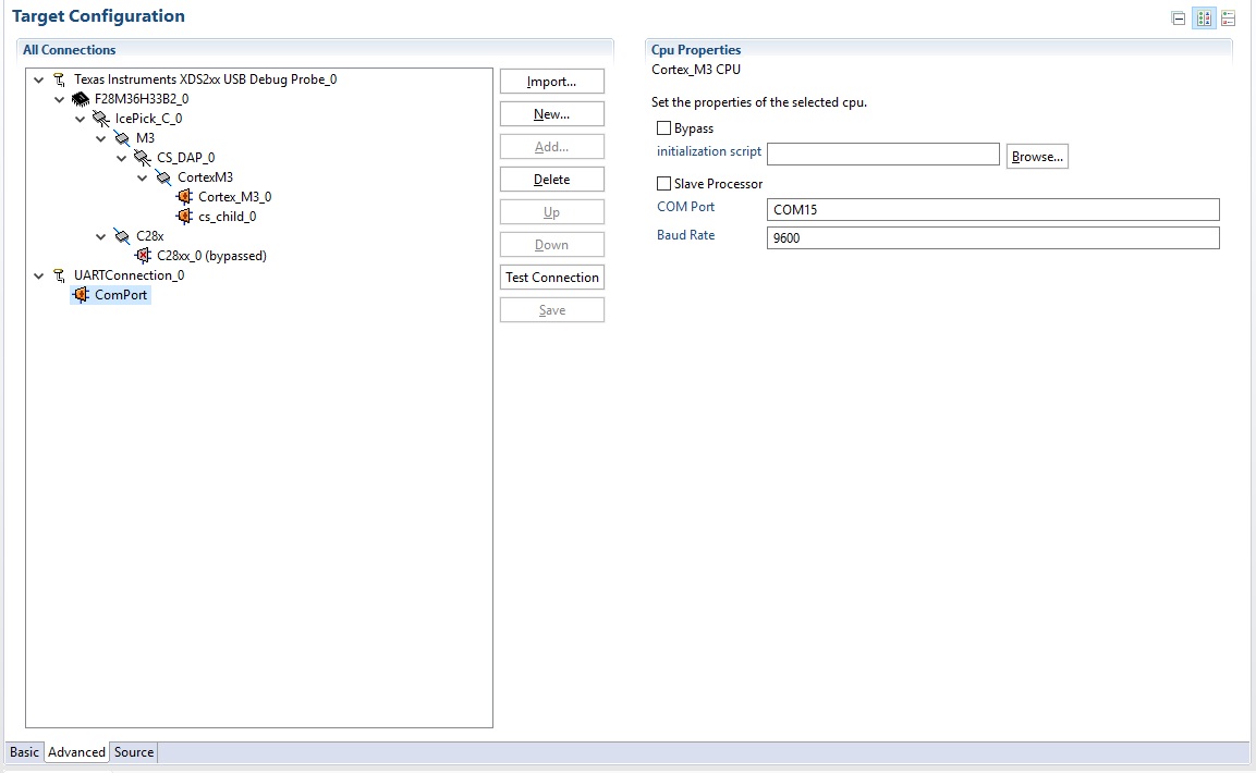
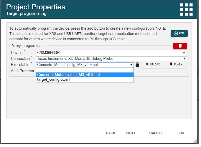
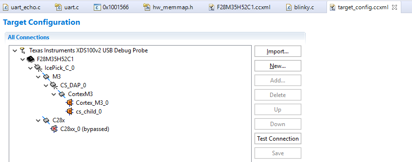
I am trying to get my Gui Composer application to connect with USB-UART. I have added the serial monitor code to my target, (M3 core of the Concerto) and added the USB-UART communication monitor in the Gui properties. I am able to get it working in CCS by doing the following: my target is running from either flash or ram,I add Uart communication in the configurations file and then load symbols to the UARTConnection in the debug view. I can then view all variables in the expressions window, and if I export my gui to CCS desktop view and run it from CCS it connects to my target and updates the values. However, I am not able to get the UART connection working while running the gui from the gui composer cloud web interface or when exporting the gui to standalone app. In both cases I only get an error: "TICloudAgent Config Error:Failed to connect to F28M36H33B2 device: Please unplug your hardware, then plug it back in and try again". The latter is actually what I would like to do, to have a stand-alone app that connects to the target using USB-UART. Note that the xds connection works perfectly from the cloud and from CCS. Why would the USB-UART connection work in CCS but not the stand-alone app or from the cloud? 

  • Hi Albert,

    Can you explain what you mean when you say, " I am not able to get the UART connection working while running the gui from the gui composer cloud web interface or when exporting the gui to standalone app" ?

    Are you able to load the symbols/program into the device properly? Is it just that the UART/SCI communication is not being received by the GUI composer cloud interface or when exporting to the standalone app?

    Have you been successful in communicating over UART/SCI to the GUI cloud or standalone with other programs?

    I am not very familiar with the GUI composer or cloud tools. This may be an issue with the tool, but I want to rule our SCI or program issues first.

    sal
  • Hi Albert, 

    In addition to what Sal mentioned, I wonder if the difference is that GUI Composer is not picking correct COM port, when running online or standalone. You could add Options menu to your application that allows to select a different COM port. You would need to: in widgets pallette there is an "options" menu which you can drag and drop into your app. When you run the application you should be able to click on that "Options" menu to bring up a dialog that allows you to adjust selected COM port and baud settings (you should be able to adjust these in Project Propeties as well). You would be able to verify that the same COM port is used in CCS and GUI Composer when GC runs online or standalone. 

    Martin

  • Can you explain what you mean when you say, " I am not able to get the UART connection working while running the gui from the gui composer cloud web interface or when exporting the gui to standalone app" ? 

    My Gui only connects to the target device when exported to CCS desktop view, not any of the other methods of running the gui. 

    Are you able to load the symbols/program into the device properly?

    Yes. With CCS desktop view I load the symbols and then it connects correctly. With the cloud interface I click the auto load checkbox in properties, it loads the program successfully but does not connect (variables does not get updated). With the standalone app I pre-load the program into flash and let it run, then try to connect the app to the target but it does not connect (variables does not get updated).  

    Is it just that the UART/SCI communication is not being received by the GUI composer cloud interface or when exporting to the standalone app?

    Both. I get no communication between the gui and the target when using the cloud interface or the standalone app.


    Have you been successful in communicating over UART/SCI to the GUI cloud or standalone with other programs?

    No I have not done this before.

    I am not very familiar with the GUI composer or cloud tools. This may be an issue with the tool, but I want to rule our SCI or program issues first.

    I don't think the problem lies with the SCI program since it is working fine when I run the gui in CCS Desktop view.

  • Yes I already added the options menu and selected the correct COM port.
  • Hi Albert,

    I'll be away for couple of days but I'll try to see if I can reproduce this issue on our end when I get back. As an additional test, would you be able to see if you get the same behaviour if try to disable auto programming? 

    Martin

  • Yes I have done this as well and unfortunately it does not make a difference.

  • HI Albert, 

    This is taking a bit longer than anticipated. However, we are speculating that GUI Composer is using the wrong core for expression evaluation. Symbols (i.e. .out file) provide global variable names, etc, However, there is a core type set of information that provide things like addressing mode, endiannes, word size, etc. I believe that GC is using 28x information to resolve/evaluate M3's symbols. 

    When you run in CCS, that selection is bypassed because an app will use whatever is selected in Debug View. 

    There is a way of working around this, but creating a custom target configuration file in CCS and then using it in GC. You would need to start CCS and create a new target configuration using CCS Setup program, choose your debug probe and device, then go to advanced tab, select 28x core and click bypass. Save this as "target_config.ccxml" then use instructions here


    If link above does not work, then you would need to open GUI Composer Users Guide from Help menu and then select XDS link and scroll down to "Custom target configuration file" to upload this modified ccxml to your GC app. Bypassing 28x core should force GC to use M3 for expression evaluation. 

    Martin

  • Hi Martin

    Thanks for the suggestion. I am trying to do this but I am not sure if I am uploading it correctly. I don't have a "Target Program/Symbols" section on the Target Communication page to upload the .ccxml file to, as it describes in the User Guide.

    I did however uploaded the .ccxml file by right click/ add file in the project explorer on the left in Gui composer. It still did not seem to work though. It still does not connect to the target with UART.

  • Hi Albert, 

    I thought those instructions were accurate, but they are not. I'll file a bug to update User's Guide. The sequence of steps would be roughly the same but on previous page in the wizard. i.e. in the section where you upload .out file, you would need to click on "Upload" then choose target_config.ccxml from you local disk. This will upload that file and store it "targets" directory it is not visible in Projects View in GC, once that file is uploaded, click on drop down (you should now see two entries one with .out and second with .ccxml) and choose .out. 

    In summary we are uploading two files, but we still want executable to have the .out selection as active. 

    If you choose file->Export as project, and inspect generated .zip file you should be able to see .out and .ccxml in that "target" subdirectory that I mentioned. 

    Martin

  • Hi Martin

    I followed your new instructions but it still does not work. Here is what I did:

    I created the config file in ccs to have a UART connection and to bypass c28.

    If I now launch this new configuration in CCS and load my program onto the target, either RAM or Flash, and load symbols on the UART connection, I am able to see all variables updating in expressions view and on my Gui.

    Then I upload this config file to my Gui composer project as per your instructions.

     Auto Program is not checked. I also have a USB_UART communication setup.

    Then I run the Gui from the cloud. It tries to connect and then ends with a "Hardware not connected" message. This is also the same case if I Export the Gui to Stand-alone app and run it. I Only get a "Hardware not connected". I also configure the serial port in the Gui.

  • Hi Albert, 

    I was thinking of a custom configuration that looks like a picture below. It is a little bit different than what you have. Rest of your configuration steps look ok. With custom target_config.ccxml I was trying to eliminate 28x from the picture. 

    I have a slightly different control card 28M35HC52 with XDS100v2, I verified that JTAG based approach works with a config as shown below. However, I am having trouble getting simple UART example to work. I tried uart_echo example from ControlSuite, but it does not work as expected. Thus I am not able yet to try and duplicate your setup. 

    Martin

  • Hi Martin

     I have made a target config just like yours and it does not work. How should I proceed from here? I really need to deploy the gui as a standalone application using UART monitor comms.

  • target_config.ccxmlHi Albert,

    I have been struggling with our board and getting a simple UART echo example to work. I don't see any output from our control card.

    I lead you the wrong path with how to create a custom xml file. I have synched up with another engineer and we believe that attached file should work. However, I still have not been able to get my board to work, thus I can't confirm that it will work. However, would you be willing to try one more file? Please download attached ccxml, You probably will need to delete the one that was previously uploaded and then upload this new one. You should have only one target_config.ccxml file. Please let me know if this works and I can explain how this was created, if you are interested.

    Martin

  • Hi Martin

    Thanks for the file. It seems that we are making progress but not yet there. I have uploaded the config file and started the gui. This is the message that I got after it tried to connect:

    Connected to TI Cloud Agent.Connecting to target ...

    Error downloading program symbols: Encountered a problem loading file: C:..../Temp/ti_cloud_storage/F28M36H33B2.data Could not determine target type of file Please unplug your F28M36H33B2, then plug it back in and try again.

    Then I opened the config file in CCS and changed the device to F28M36H33B2 (it was on F28M36P53C2) and left everything else in the file exactly the same. I uploaded the file again and started the gui again. This is the messages that I got this time:


    Connected to TI Cloud Agent.Connecting to target ...
    COM15:9600 verifying connection...
    Communication with Target Failed: Target failed to read 0x200053C8

    Can't get it to work any further that that. Do you why it gives this error?


  • Hi Albert,

    I work with Martin and he will be await for the next few days. I'll try to see if I can help you with this issue in the mean time.

    Can you tell me what is the baud rate that you are expecting to use for your device? From the error message that you have above, it is using COM15 with baud rate 9600. Does this match your device's setting?

    Patrick
  • Thanks Patrick

    Yes the baud rate and com port is correct and are the same as when I connect the gui with CCS desktop view, which works fine.

    I also need to mention that during the connection period, when using your config file, at some point my target device stops running for some reason. 

    regards

    Albert

  • Can you enable the ticloudagent logging and attach the logs here?

    You can enable logging by removing REM from the SET lines in this file <user.home>\TICloudAgent\ticloudagent.bat. 
    Reload the browser page to pickup the change in the bat file.

    Regards,
    Patrick

  • Albert,

    I am trying to reproduce your issue, but I don't have the target code setup for the serial monitor. Do you have A M3 test project that you can upload here? It will greatly reduce the time that I need to setup a build-able project and then use it to debug the issue with GUI Composer communication issue.

    Patrick
  • Patrick

    Here are the log files and a very simple M3 project with the serial monitor added. It has a global variable "CycleCounter" which you can bind to the gui and you should see it counting. I have tested it with CCS desktop view and it works when connected over UART.

    GuiComposerUART_Test_M3.ziplogs.zip

  • Hi Albert,
    Thanks for the project and I am able to reproduce the issue. I'll need sometime to investigate the issue and I'll get back to you as soon as I can.

    Patrick
  • Hi Albert,
    I am a similar device as what you have. However, I am not able to use UARTConnection to read the variable with your program. Can you also provide the ccxml file that you use in CCS to communicate with the device?

    Patrick
  • Hi Patrick

    Here is the ccsxml file that I use.

    config.zip

  • Hi Albert,

    Thanks for the ccxml file. I have a similar device as you have and I have been struggling to get the program to run in flash after power cycling the device. I am working with our C2000 team on the flash issue.

    Do you have multiple COM ports for your program or other COM port that is visible in Windows device manager? If you do, you will need to make sure that you have selected the correct COM port when you run your GUI Composer app.

    Here are the steps to add a COM port selection widget to your application and select the COM port when your run the application:

    • In the Palette, enter option in the search box. Drag the Options Menu widget to your applications menu bar. The Options menu might not be correctly added to the position that you drop it into. You can fix this by switching to the HTML mode and move the option tag to the desired location in the menu.
    • Run the application
    • Select the Options/Serial Ports to open the COM selection dialog and choose the correct port

    In the GUI Composer designer, make sure that you don't reflash your device. We don't currently have a way to flash the device with custom ccxml file. We are working on this feature. In the project properties dialog, navigate to the Target programming page. Make sure the Auto Program checkbox is unchecked, but keep the programloader to load symbols for the target monitor.

    I also have adjusted the ccxml file that you have attached, it is similar to the one that Martin sent. But we don't need to include other core to be bypassed. Having the UARTConnection with the M3 core is sufficient. Please upload the attached ccxml to your application. You can upload this file the same way you upload the executable in the Target programming page. Make sure that you select your device program in the droplist after you have uploaded the target_config.ccxml file.

    Let me know if this help you to progress any further. In the mean time, I'll try to get my device working.

    0385.target_config.ccxml

    Regards,
    Patrick

  • Hi Patrick

    I followed your instructions as above and still don't get it to work.

    I have the COM port selection widget and it is selecting the correct COM port. I have the Auto Program checkbox Unchecked. I have my device program selected in the droplist after uploading the target_config.ccxml file.

    It now does not give error message and only gives a message saying "Hardware connected", but nothing is being updated on the GUI as if the symbols are not loaded.

    Just something I notice, when using your config file in CCS desktop view, it does not connect when I load the symbols from the flash configuration. But it does work when I load the symbols from the RAM configuration. In the cloud version, however, neither of them work.

    Regards

    Albert

  • Hi Albert,

    Sorry for taking so long, I was time sharing the device that for tracking down this issue. The ccxml file that I gave you doesn't specify the com port, it it meant for GUI Composer.

    When you flash your device onto FLASH, make sure that you can communicate with your device after it is power cycled. Try the following steps to see if you can communicate with your device in CCS first before using it in GUI Composer.

    1. Flash the device using XDS.
    2. Terminate the debug session in CCS.
    3. Power cycle your device.
    4. Connect to your device with UARTConnection only with the 28x bypassed, this is important step.
    5. Load symbol (not program) onto the M3 device.
    6. Use expression view to read/write a variable.

    Once this is working, GC should be able to handle your application. For my device, F28M35H52C1, I have to configure the device by setting the onboard switches to boot from FLASH. Make sure your device have the correct setting to boot from FLASH.

    After struggle with a bad board, figuring out the onboard switches to boot from FLASH. I was able to get my program working in GC. I have attached a working example with the F28M35H52C1 device, both the CProject and GCProject.

    The CProject is an example from control suite with the monitor added, Serial_Cmd_Monitor.h/.c.  I added the gcTest global variable as well as calling the receivedDataCommand monitor function in the usb_dev_serial.c file (line 154).

    The GCProject has two checkboxes, both binds to gcTest variable. The CCXML file is specific to my device, you will need to modify it to fit your device. It might just work without any change.

    To test the GCProject, make sure you flash the binary in the CProject onto your device first using XDS. And than use the GCProject. You do need to make sure you select the correct com port in the GCApplication when it is in running. The com port selection is in the Help -> Options menu.

    If you can't get this to work, we can have a webex session. I can walk you through the steps.

    Application.zip

    usb_dev_serial_m3.zip

    Regards,
    Patrick

  • Hi Patrick.

    Thanks for taking the time to help me sort out this, I finally got it to work.

    Here is what I did this time:
    I took your GCProject and imported it into my account. I din't use your CProject at all, I just left my target as is with my own project running. Then on your GCProject I just added another widget and linked it with a variable that I had in my target project already. I then uploaded my target project program (.out) file so that it will have the correct symbols. I ran the Gui and it worked perfectly over UART.

    Then I went back to my own GCProject and made sure everything is setup exactly as your GCProject in the Properties dialog. I also uploaded your target_config.ccxml file into my GCProject. So in theory this should now be exactly the same as your project but only with my own widgets. But it didn't work! I still don't know why.

    Then I literally copied the contents of my index.gui and newfile_0.js files into your project to override yours and essentially put all my widgets into your project. I just had to re-bind all my widgets to variables. I ran it and everything worked fine!

    So I don't know what was the problem with my GCProject. It was setup exactly like yours with the same target_config.ccxml file but it did not want to work. Perhaps something to do with the binding, although it worked in CCS Desktop view. Anyways, I am glad it is working now.

    Thanks again for the help.

    Regards
    Albert