This thread has been locked.

If you have a related question, please click the "Ask a related question" button in the top right corner. The newly created question will be automatically linked to this question.

BOOSTXL-BUCKCONV: Could I add more coefficients ??

Part Number: BOOSTXL-BUCKCONV
Other Parts Discussed in Thread: CONTROLSUITE

Hi,

I just purchased this buck converter and LAUNCHSL-F28069M. I am wondering if I could add more coefficients for the compensator. Images below are found in the document whose link is shown also below.

http://www.ti.com/lit/ug/spruhz5a/spruhz5a.pdf


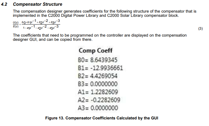
Looks like it can handle up to three pole three zero. Is there any way I can work with four pole four zero?? 

Thanks,

Yuki

  • This compensator can have a maximum of 3 pole 3 zeros. This should be enough for a buck converter control. You can create a new 4 pole 4 zero compensator if you need it. The code will change accordingly. But, again we don't see a need for that for a buck converter control.

    Shamim

  • Shamim,

    Thanks you for your reply. It's much appreciated.
    I would like to follow up with a couple more questions:

    1) You said "You can create a new 4 pole 4 zero compensator 
    if you need it. The code will change accordingly."

    Can you please direct me to some documentation that shows
    what needs specifically to be done to change the code 
    appropriately?


    (By the way, I'm also considering using the digital controller 
    with a higher order converter.)


    2) I see that I can change the switching frequency by 
    setting the variable 'BUCK_PWM_SWITCHING_FFREQUENCY' in
    the code. Is there a way to change the Sampling
    Frequency? Looking at the Tustin transformation results
    I was able to deduce that a 50 kHz sampling frequency 
    appears to be the default, but where is that set?


    Thanks, in advance.

    Yuki
  • The documentation is in the lib folder. I am attaching the doc. Look the the code and see how it changes from 2p-2z to 3p-3z. Then it should be clear how you make it 4p-4z.

    For Sampling freq change you need to change the ISR initialization in Buck_MVC-Main.c.

    //====================================================================================
    // INTERRUPTS & ISR INITIALIZATION (best to run this section after other initialization)
    //====================================================================================
    // Set up C28x Interrupt

    EALLOW;
    // Configure selected PWM to issue interrupts
    #if BUCK_PWM_NO==1
    PieVectTable.EPWM1_INT = &DPL_ISR_wFRA; // Map Interrupt
    PieCtrlRegs.PIEIER3.bit.INTx1 = 1; // PIE level enable, Grp3 / Int1
    #elif BUCK_PWM_NO == 2
    PieVectTable.EPWM2_INT = &DPL_ISR_wFRA; // Map Interrupt
    PieCtrlRegs.PIEIER3.bit.INTx2 = 1; // PIE level enable, Grp3 / Int2
    #elif BUCK_PWM_NO == 3
    PieVectTable.EPWM3_INT = &DPL_ISR_wFRA; // Map Interrupt
    PieCtrlRegs.PIEIER3.bit.INTx3 = 1; // PIE level enable, Grp3 / Int3
    #elif BUCK_PWM_NO == 4
    PieVectTable.EPWM4_INT = &DPL_ISR_wFRA; // Map Interrupt
    PieCtrlRegs.PIEIER3.bit.INTx4 = 1; // PIE level enable, Grp3 / Int4
    #elif BUCK_PWM_NO == 5
    PieVectTable.EPWM5_INT = &DPL_ISR_wFRA; // Map Interrupt
    PieCtrlRegs.PIEIER3.bit.INTx5 = 1; // PIE level enable, Grp3 / Int5
    #endif
    ePWM[BUCK_PWM_NO]->ETSEL.bit.INTSEL = ET_CTR_PRD; // INT on PRD event
    ePWM[BUCK_PWM_NO]->ETSEL.bit.INTEN = 1; // Enable INT

    #if CNTRL_ISR_FREQ_RATIO == 1
    ePWM[BUCK_PWM_NO]->ETPS.bit.INTPRD = ET_1ST; // Generate INT on every event
    #elif CNTRL_ISR_FREQ_RATIO == 2
    ePWM[BUCK_PWM_NO]->ETPS.bit.INTPRD = ET_2ND; // Generate INT on every event
    #elif CNTRL_ISR_FREQ_RATIO == 3
    ePWM[BUCK_PWM_NO]->ETPS.bit.INTPRD = ET_3RD; // Generate INT on every event

    Shamim

  • Hi Shamim,

    Thank you for your reply. I have a few more questions. 

    Are switching frequency and sampling frequency set independently? Or is one related to the other one? For example, say when the switching frequency is 200kHz, the sampling frequency is 50kHz. Does changing the switching frequency to 100kHz result in lowering the sampling frequency to 25kHz??

    In the code you posted, what indicates what the sampling frequency is? Could you give me an example for what to change if I want the sampling frequency to be 25kHz?

    I would be much appreciative for any further help you can offer.

    Yuki

  • Yes, those can be set independently. You can make switching and sampling freq the same. Or you can make sampling 1/2 or 1/4th of switching frequency.

    Sampling freq should not be any lower than 1/4th of switching. Then the control loop performance will degrade.

    Please check in the code where the interrupt is set up. The frequency of that interrupt is the sampling frequency. This code was written by someone several years ago. So you need to review this fully to determine the sampling frequency.

    Shamim

  • Shamim,

    In your penultimate post above you refer to "The documentation is in the lib folder. I am attaching the doc."

    Unfortunately I did not find the doc as an attachment or otherwise. Could you please guide me to find it?

    At the present stage I have my own controller coefficients for both 2p-2z and 3p-3z configurations which I would like to test with the TI buck converter. I tried changing the coefficients directly in the "main.cfg" file, as well as in the "Buck_VMC-Settings.h" but this was unsuccessful.

    Any further help would be much appreciated.

    Yuki

  • Please see the attached file. If you install ControlSUITE then it will be in the following folder:

    C:\TI\controlSUITE\libs\app_libs\digital_power\f2803x_v3.5\Doc

    Shamim

    0724.DPLib.pdf