Hi,
I have several questions about the picture below:
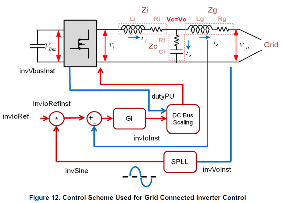
1. Vc=Vo is wrong here for grid connected inverter, right?
2. Zf in Figure 13 is Zc in Figure 12, right?
3. What does Kvdc_fbk and Gd means in Figure 13?
4. The equation from Vi to Io in Figure 13 should be reciprocal of the equation existing, right?
5. For grid connected inverter, we can use Zi only, right? What's the benefit for adding Zi, Zc, Zg (LCL in the circuit)?