This thread has been locked.

If you have a related question, please click the "Ask a related question" button in the top right corner. The newly created question will be automatically linked to this question.

CCS/TMDSDOCK28379D: the frequency of output PWM signal become high when i set EPWM1.TBCTL[PHSEN]=1?

Part Number: TMDSDOCK28379D
Other Parts Discussed in Thread: TMS320F28379D

Tool/software: Code Composer Studio

Now I'm using the digital compare trip(DC) TZ1 to generate a DCAEVT1.sync signal to my PWM module and I found in the datasheet I must set the PHSEN to 1 as following figures:

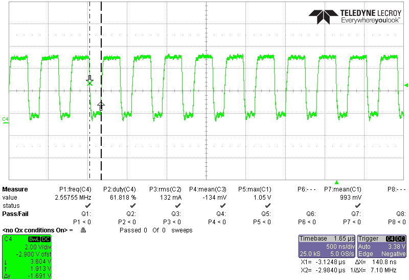
But when I set the PHSEN of EPWM1 to 1, I found the frequency of output waveform become higher, as you can see in the below pictures before and after I set the PHSEN to 1;

before I set PHSEN to 1, the frequency is 1MHz as I want(EPWMCLK=100MHz, TBPRD=99), But after I set the PHSEN to 1, the frequency becomes to 2.5MHz, so what's the problem and should PHSEN of EPWM1 must set to 0? 

  • As you can see in the diagram above, there are multiple signals ORED with DCAEVT1.sync that can cause your PWM Timebase to reset. There are more sync events occuring than you are expecting. Check those signals. If your timebase keeps resetting because of these events, then you are basically shortening your period, causing a higher frequency than the one desired.

  • Hi, Nima,

    1. I check all the sync signal but found nothing in my program.

    2. then I found something strange when I set the AQCTLA of ePWM1 as below, the problem disappears. 

    EPwm2Regs.AQCTLA.bit.ZRO = AQ_SET;
    EPwm2Regs.AQCTLA.bit.CAU = AQ_CLEAR; 

    the output frequency is 1MHz, and the duty cycle is right.

    but when I set the AQCTLA of ePWM1 as below, the problem occurs.

    EPwm2Regs.AQCTLA.bit.ZRO = AQ_CLEAR;
    EPwm2Regs.AQCTLA.bit.CAU = AQ_SET; 

    the output frequency is 2.5MHz, and the duty cycle is wrong.

    and then I also run the TI example code in control Card TMS320F28379D, it has the same phenomenon. so any ideas about this problem?

  • That could occur if CAU value is less than the TB reseting event. Basically your sync signal occurs before CAU?

  • Hi, Nima,

    This phenomenon occurs even I didn't give the sync signal, I just set EPWM1.TBCTL[PHSEN]=1,

    when I set the AQCTLA of ePWM1 as below, the frequency is right. 

    EPwm2Regs.AQCTLA.bit.ZRO = AQ_SET;
    EPwm2Regs.AQCTLA.bit.CAU = AQ_CLEAR; 

    the output frequency is 1MHz, and the duty cycle is right.

    but when I set the AQCTLA of ePWM1 as below, the problem occurs.

    EPwm2Regs.AQCTLA.bit.ZRO = AQ_CLEAR;
    EPwm2Regs.AQCTLA.bit.CAU = AQ_SET;

    the output frequency is 2.5MHz, and the duty cycle is wrong.


    I test in several TI example code and I found this is the common problem.

  • Epwm1 using gpio0?

  • Yes, ePWM1 use GPIO0 and GPIO1, anything wrong with this pin?

  • No but you’re not taking care of you inputxbar.

    Extayncins are by default connected to inputxbar5 and 6 which are by default connected to gpio0. So that’s what is causing all of this. Change the input bar 5/6 to use gpio ,let’s say 50.

    That will fix everything.

  • Hi Nima,

    Thanks so much, i will try it and wish you a good weekend.

  • This is the code snippet that should fix your issue. I saw it today when I was coding and though posting it might help you save some time.

        // CHANGE XBAR inputs from using GPIO0
        // if EPWM SYNCIN is enabled, EXTSYNCIN1 and EXTSYNCIN2 will use
        // GPIO0 (which is the output of EPWM1).
        // Pick and unused GPIO
        XBAR_setInputPin(XBAR_INPUT5, 50);
        XBAR_setInputPin(XBAR_INPUT6, 50);