This thread has been locked.

If you have a related question, please click the "Ask a related question" button in the top right corner. The newly created question will be automatically linked to this question.

TMS320F28377S: AQCTLA [ZRO] event is not executed when "0" is loaded to TBCTR

Part Number: TMS320F28377S
Other Parts Discussed in Thread: TMS320F28377D, TEST2

Hi everyone,

AQCTLA [ZRO] event is not executed when "0" is loaded to TBCTR.

Is this behavior correct?

// Included Files
//
#include "F28x_Project.h"

//
// Defines
//
#define EPWM1_MAX_DB   0x03FF
#define EPWM2_MAX_DB   0x03FF
#define EPWM3_MAX_DB   0x03FF
#define EPWM1_MIN_DB   0
#define EPWM2_MIN_DB   0
#define EPWM3_MIN_DB   0
#define DB_UP          1
#define DB_DOWN        0

//
// Globals
//
Uint32 EPwm2TimerIntCount;
Uint16 EPwm2_DB_Direction;

//
// Function Prototypes
//
void InitEPwm2Example(void);

__interrupt void epwm2_isr(void);


//
// Main
//
void main(void)
{

    InitSysCtrl();

    CpuSysRegs.PCLKCR2.bit.EPWM2=1;

    InitEPwm2Gpio();

    DINT;
    InitPieCtrl();
    IER = 0x0000;
    IFR = 0x0000;

    InitPieVectTable();

    EALLOW; // This is needed to write to EALLOW protected registers
    PieVectTable.EPWM2_INT = &epwm2_isr;
    EDIS;   // This is needed to disable write to EALLOW protected registers

    EALLOW;
    CpuSysRegs.PCLKCR0.bit.TBCLKSYNC =0;
    EDIS;

    InitEPwm2Example();

    EALLOW;
    CpuSysRegs.PCLKCR0.bit.TBCLKSYNC =1;
    EDIS;

    EPwm2TimerIntCount = 0;

    IER |= M_INT3;


    PieCtrlRegs.PIEIER3.bit.INTx2 = 1;

    EINT;  // Enable Global interrupt INTM
    ERTM;  // Enable Global realtime interrupt DBGM

    for(;;)
    {
        asm ("          NOP");
    }
}


//
// epwm2_isr - EPWM2 ISR
//
__interrupt void epwm2_isr(void)
{

    EPwm2TimerIntCount++;

    EPwm2Regs.TBCTR = 0;
    //
    // Clear INT flag for this timer
    //
    EPwm2Regs.ETCLR.bit.INT = 1;

    //
    // Acknowledge this interrupt to receive more interrupts from group 3
    //
    PieCtrlRegs.PIEACK.all = PIEACK_GROUP3;
}


//
// InitEPwm2Example - Initialize EPWM2 configuration
//
void InitEPwm2Example()
{
    EPwm2Regs.TBPRD = 6000;                       // Set timer period
    EPwm2Regs.TBPHS.bit.TBPHS = 0x0000;           // Phase is 0
    EPwm2Regs.TBCTR = 0x0000;                     // Clear counter

    //
    // Setup TBCLK
    //
    EPwm2Regs.TBCTL.bit.CTRMODE = TB_COUNT_UP; // Count up
    EPwm2Regs.TBCTL.bit.PHSEN = TB_DISABLE;        // Disable phase loading
    EPwm2Regs.TBCTL.bit.HSPCLKDIV = TB_DIV4;       // Clock ratio to SYSCLKOUT
    EPwm2Regs.TBCTL.bit.CLKDIV = TB_DIV4;          // Slow just to observe on
                                                   // the scope

    //
    // Setup compare
    //
    EPwm2Regs.CMPA.bit.CMPA = 3000;
//    EPwm2Regs.CMPB.all = 4500;

    //
    // Set actions
    //
    EPwm2Regs.AQCTLA.bit.ZRO = AQ_CLEAR;          // Set PWM2A on Zero
    EPwm2Regs.AQCTLA.bit.CAU = AQ_SET;

    //
    // Interrupt where we will modify the deadband
    //
    EPwm2Regs.ETSEL.bit.INTSEL = ET_CTRU_CMPA;     // Select INT on Zero event
    EPwm2Regs.ETSEL.bit.INTEN = 1;                // Enable INT
    EPwm2Regs.ETPS.bit.INTPRD = ET_3RD;           // Generate INT on 3rd event
}


//
// End of file
//

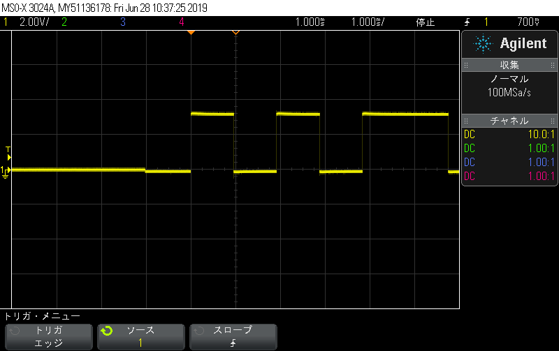
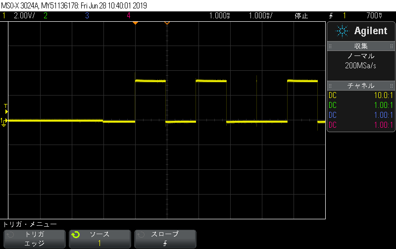
I checked with the above source code.

AQCTLA [ZRO] event  was not executed when TBCTR = 0 in the interrupt function.

Please let me know if there is a method to execute AQCTLA [ZRO] event when TBCTR = 0.

Best regards,

Sasaki

  • Hi,

    I think there is some ambiguity in the epwm configuration. Why is the counter set to 0 in epwm ISR? The pwm action is set on CAU & zero and the interrupt is configured to trigger at CMPA. Please check if this what is intended. You may have to remove the TBCTR = 0 statement in ISR.

    Thanks

    Vasudha

  • Hi Vasudha-san,

    Thank you for your reply.

    Vasudha Bhadoria said:
    Why is the counter set to 0 in epwm ISR?

    I received an inquiry from the customer that setting TBCTR to 0 would pass  AQCTLA [ZRO] event.

    In order to test this, I created a program to set TBCTR  to 0 in ISR.

    Vasudha Bhadoria said:
    The pwm action is set on CAU & zero and the interrupt is configured to trigger at CMPA. Please check if this what is intended.

    This is a program to reproduce the customer's problem. So this is what I intended.

    The AQCTLA [ZRO] event will not be executed if TBCTR is loaded with "0".

    Please let me know why it looks like this.

  • There is one more question in addition.

    My customer has the following settings:

    • Active Period Reg Load from Shadow Reg . (TBCTL[PRDLD] = 0)
    • Shadow to Active Load of TBPRD occurs only when TBCTR = 0. (TBCTL2[PRDLDSYNC] = 0)

    Then, if TBCTR is set to 0 after setting TBPRD, the TBPRD value is not loaded from the Shadow Reg to the Active Reg immediately.
    The Shadow Reg is loaded into the Active Reg when TBCTR = 0 for the next cycle.

    Why is this behavior?

  • Hi Vasudha-san,

    As I found new information, I add it to the following.

    The AQCTLA[ZRO] event is not executed when "0" is written to TBCTR Reg,
    but this event is executed when "0" is loaded from TBPHS to TBCTR using TBCTL[SWFSYNC](Software Forced Sync Pulse).

    Can you tell why the behavior is different for these two patterns

  • Hi,

    I executed the provided code and could see AQCTLA[ZRO] event getting executed when counter is set to zero in ISR. You can also verify this by seeing the change in duty of the resultant signal.

    Thanks

    Vasudha

  • Hi Vasudha-san,

    Thank you for your support.

    Vasudha Bhadoria said:
    I executed the provided code and could see AQCTLA[ZRO] event getting executed when counter is set to zero in ISR.

    ould like to test in the same environment as you, so please tell me the board you used.

    I used the LAUNCHXL-F28377S.

  • Hi Vasudha-san,

    My customer wants to solve this problem quickly.

    Could you please teach me the board you used.

    Also, please send the ccs project you used if possible.

    Best regards,

    Sasaki

  • Hi Sasaki,

    I have used TMS320F28377D VDB board for testing the same. I dont think this should depend on the board used.

    Can you let me know the frequency and duty values you are getting after executing the above code?

    Thanks

    Vasudha

  • Hi Vasudha-san,

    Thank you for your support.

    The following is the result of my test.

    (1) Test to update TBCTR directly to 0 in program

    // Included Files
    //
    #include "F28x_Project.h"
    
    //
    // Defines
    //
    
    //
    // Globals
    //
    Uint32 EPwm2TimerIntCount;
    Uint16 EPwm2_DB_Direction;
    
    //
    // Function Prototypes
    //
    void InitEPwm2Example(void);
    
    __interrupt void epwm2_isr(void);
    
    
    //
    // Main
    //
    void main(void)
    {
    
        InitSysCtrl();
    
        CpuSysRegs.PCLKCR2.bit.EPWM2=1;
    
        InitEPwm2Gpio();
    
        DINT;
        InitPieCtrl();
        IER = 0x0000;
        IFR = 0x0000;
    
        InitPieVectTable();
    
        EALLOW; // This is needed to write to EALLOW protected registers
        PieVectTable.EPWM2_INT = &epwm2_isr;
        EDIS;   // This is needed to disable write to EALLOW protected registers
    
        EALLOW;
        CpuSysRegs.PCLKCR0.bit.TBCLKSYNC =0;
        EDIS;
    
        InitEPwm2Example();
    
        EALLOW;
        CpuSysRegs.PCLKCR0.bit.TBCLKSYNC =1;
        EDIS;
    
        EPwm2TimerIntCount = 0;
    
        IER |= M_INT3;
    
    
        PieCtrlRegs.PIEIER3.bit.INTx2 = 1;
    
        EINT;  // Enable Global interrupt INTM
        ERTM;  // Enable Global realtime interrupt DBGM
    
        for(;;)
        {
            asm ("          NOP");
        }
    }
    
    
    //
    // epwm2_isr - EPWM2 ISR
    //
    __interrupt void epwm2_isr(void)
    {
    
        EPwm2TimerIntCount++;
    
    //    EPwm2Regs.TBCTL.bit.SWFSYNC = 1;
        EPwm2Regs.TBCTR = 0;
        //
        // Clear INT flag for this timer
        //
        EPwm2Regs.ETCLR.bit.INT = 1;
    
        //
        // Acknowledge this interrupt to receive more interrupts from group 3
        //
        PieCtrlRegs.PIEACK.all = PIEACK_GROUP3;
    }
    
    
    //
    // InitEPwm2Example - Initialize EPWM2 configuration
    //
    void InitEPwm2Example()
    {
        EPwm2Regs.TBPRD = 6000;                       // Set timer period
        EPwm2Regs.TBPHS.bit.TBPHS = 0x0000;           // Phase is 0
        EPwm2Regs.TBCTR = 0x0000;                     // Clear counter
    
        //
        // Setup TBCLK
        //
        EPwm2Regs.TBCTL.bit.CTRMODE = TB_COUNT_UP; // Count up
        EPwm2Regs.TBCTL.bit.PHSEN = TB_ENABLE;        // Disable phase loading
        EPwm2Regs.TBCTL.bit.HSPCLKDIV = TB_DIV4;       // Clock ratio to SYSCLKOUT
        EPwm2Regs.TBCTL.bit.CLKDIV = TB_DIV4;          // Slow just to observe on
                                                       // the scope
        EPwm2Regs.TBCTL.bit.PRDLD = 0;     // PRD shadow mode
        EPwm2Regs.TBCTL2.bit.PRDLDSYNC = 0; // shadow to active load when tbctr=0
    
    
        //
        // Setup compare
        //
        EPwm2Regs.CMPA.bit.CMPA = 3000;
    //    EPwm2Regs.CMPB.all = 4500;
    
        //
        // Set actions
        //
        EPwm2Regs.AQCTLA.bit.ZRO = AQ_CLEAR;          // Set PWM2A on Zero
        EPwm2Regs.AQCTLA.bit.CAU = AQ_SET;
    
        //
        // Interrupt where we will modify the deadband
        //
        EPwm2Regs.ETSEL.bit.INTSEL = ET_CTRU_CMPA;     // Select INT on Zero event
        EPwm2Regs.ETSEL.bit.INTEN = 1;                // Enable INT
        EPwm2Regs.ETPS.bit.INTPRD = ET_3RD;           // Generate INT on 3rd event
    }
    
    
    //
    // End of file
    //
    

    (2) Test to update TBCTR to 0 with TBPHS

    // Included Files
    //
    #include "F28x_Project.h"
    
    //
    // Defines
    //
    
    //
    // Globals
    //
    Uint32 EPwm2TimerIntCount;
    Uint16 EPwm2_DB_Direction;
    
    //
    // Function Prototypes
    //
    void InitEPwm2Example(void);
    
    __interrupt void epwm2_isr(void);
    
    
    //
    // Main
    //
    void main(void)
    {
    
        InitSysCtrl();
    
        CpuSysRegs.PCLKCR2.bit.EPWM2=1;
    
        InitEPwm2Gpio();
    
        DINT;
        InitPieCtrl();
        IER = 0x0000;
        IFR = 0x0000;
    
        InitPieVectTable();
    
        EALLOW; // This is needed to write to EALLOW protected registers
        PieVectTable.EPWM2_INT = &epwm2_isr;
        EDIS;   // This is needed to disable write to EALLOW protected registers
    
        EALLOW;
        CpuSysRegs.PCLKCR0.bit.TBCLKSYNC =0;
        EDIS;
    
        InitEPwm2Example();
    
        EALLOW;
        CpuSysRegs.PCLKCR0.bit.TBCLKSYNC =1;
        EDIS;
    
        EPwm2TimerIntCount = 0;
    
        IER |= M_INT3;
    
    
        PieCtrlRegs.PIEIER3.bit.INTx2 = 1;
    
        EINT;  // Enable Global interrupt INTM
        ERTM;  // Enable Global realtime interrupt DBGM
    
        for(;;)
        {
            asm ("          NOP");
        }
    }
    
    
    //
    // epwm2_isr - EPWM2 ISR
    //
    __interrupt void epwm2_isr(void)
    {
    
        EPwm2TimerIntCount++;
    
        EPwm2Regs.TBCTL.bit.SWFSYNC = 1;
    //    EPwm2Regs.TBCTR = 0;
        //
        // Clear INT flag for this timer
        //
        EPwm2Regs.ETCLR.bit.INT = 1;
    
        //
        // Acknowledge this interrupt to receive more interrupts from group 3
        //
        PieCtrlRegs.PIEACK.all = PIEACK_GROUP3;
    }
    
    
    //
    // InitEPwm2Example - Initialize EPWM2 configuration
    //
    void InitEPwm2Example()
    {
        EPwm2Regs.TBPRD = 6000;                       // Set timer period
        EPwm2Regs.TBPHS.bit.TBPHS = 0x0000;           // Phase is 0
        EPwm2Regs.TBCTR = 0x0000;                     // Clear counter
    
        //
        // Setup TBCLK
        //
        EPwm2Regs.TBCTL.bit.CTRMODE = TB_COUNT_UP; // Count up
        EPwm2Regs.TBCTL.bit.PHSEN = TB_ENABLE;        // Disable phase loading
        EPwm2Regs.TBCTL.bit.HSPCLKDIV = TB_DIV4;       // Clock ratio to SYSCLKOUT
        EPwm2Regs.TBCTL.bit.CLKDIV = TB_DIV4;          // Slow just to observe on
                                                       // the scope
        EPwm2Regs.TBCTL.bit.PRDLD = 0;     // PRD shadow mode
        EPwm2Regs.TBCTL2.bit.PRDLDSYNC = 0; // shadow to active load when tbctr=0
    
    
        //
        // Setup compare
        //
        EPwm2Regs.CMPA.bit.CMPA = 3000;
    //    EPwm2Regs.CMPB.all = 4500;
    
        //
        // Set actions
        //
        EPwm2Regs.AQCTLA.bit.ZRO = AQ_CLEAR;          // Set PWM2A on Zero
        EPwm2Regs.AQCTLA.bit.CAU = AQ_SET;
    
        //
        // Interrupt where we will modify the deadband
        //
        EPwm2Regs.ETSEL.bit.INTSEL = ET_CTRU_CMPA;     // Select INT on Zero event
        EPwm2Regs.ETSEL.bit.INTEN = 1;                // Enable INT
        EPwm2Regs.ETPS.bit.INTPRD = ET_3RD;           // Generate INT on 3rd event
    }
    
    
    //
    // End of file
    //
    

    In the case of TEST2, the program jumps to ISR on the third rising edge of PWM and the PWM waveform goes low immediately.
    However, in the case of TEST1, the PWM waveform does not fall to Low immediately.

  • Hi Vasudha-san,

    Do you have any update?

    If there is additional information needed, please let me know.

  • Hi,

    I am looking into this and will get back shortly.

    Thanks

    Vasudha

  • Hi Vasudha-san,

    Thank you for support.

    I'll be waiting for your reply.

  • Hi,

    I think this is some undeterminitic behaviour dur to both hardware and software trying to write to TBCTR.

    I realised that if you give some delay before writing to TBCTR = 0 in ISR, you can see the expected waveform.

    __interrupt void epwm2_isr(void)
    {
        __asm("  NOP");
        __asm("  NOP");
        EPwm2TimerIntCount++;
    
    //    EPwm2Regs.TBCTL.bit.SWFSYNC = 1;
        EPwm2Regs.TBCTR = 0;
        //
        // Clear INT flag for this timer
        //
        EPwm2Regs.ETCLR.bit.INT = 1;
    
        //
        // Acknowledge this interrupt to receive more interrupts from group 3
        //
        PieCtrlRegs.PIEACK.all = PIEACK_GROUP3;
    }

    Alternatly you can write TBCTR = 5999 to get similar behaviour.

    __interrupt void epwm2_isr(void)
    {
        EPwm2TimerIntCount++;
    
    //    EPwm2Regs.TBCTL.bit.SWFSYNC = 1;
        EPwm2Regs.TBCTR = 5999;
        //
        // Clear INT flag for this timer
        //
        EPwm2Regs.ETCLR.bit.INT = 1;
    
        //
        // Acknowledge this interrupt to receive more interrupts from group 3
        //
        PieCtrlRegs.PIEACK.all = PIEACK_GROUP3;
    }

    I am still debugging this and will get back once I get more information on this.

    Thanks

    Vasudha

  • Hi Vasudha-san,

    Thank you for your support!

    I'll be waiting for your reply.

  • Hi Vasudha-san

    Do you have any update?

  • Hi,

    We discussed over this and concluded that making TBCTR = 0 or TBCTR = PRD through software can lead to inconsistent behaviour.

    When the interrupt gets generated. counter is incrementing and when we write TBCTR = 0 or PRD in ISR this leads to counter load with specific value. Since the increment and load are not synchronized with TBCLK much slower than SYSCLK, this leads to inconsistent behaviour wherein counter = 0 is not getting detected by hardware.

    Hence it is better to make counter = PRD - 1, to get consistent behaviour.

    The latter case with SWSYNC works because it is being done by hardware on next TBCLK.

    Let me know if this resolves your query.

    Thanks

    Vasudha

  • Hi Vasudha-san,

    Thank you for your special support!

    I understood the mechanism. I will contact the customer to use PRD-1.