This thread has been locked.

If you have a related question, please click the "Ask a related question" button in the top right corner. The newly created question will be automatically linked to this question.

TMS320F28374D: Using the DCCAP of the Digital Compare SubModule, to measure the Ton generated by Analog Comparator

Part Number: TMS320F28374D

Good evening,

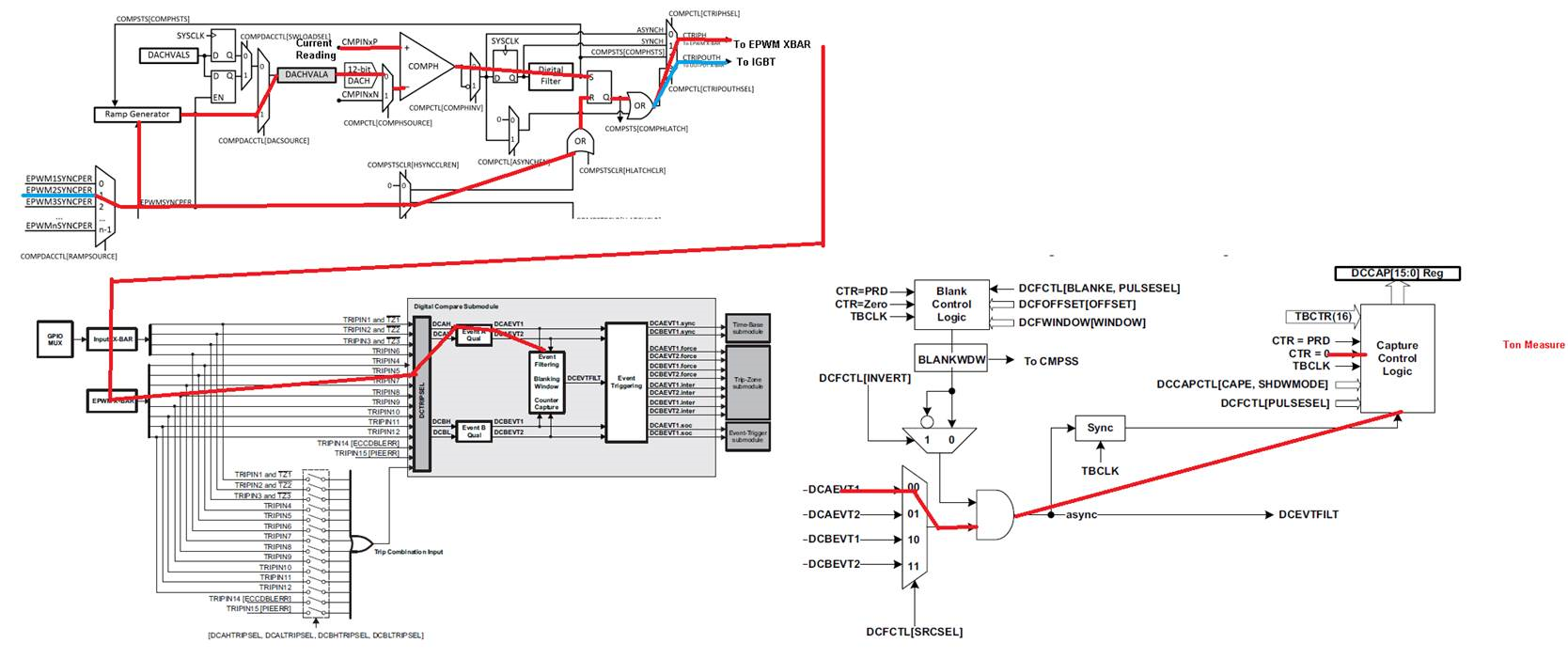
I would like to measure the Ton period generated by an analog comparator, reset by the CRT=0 event of a PWM, using the DCCAP register of the Digital Compare Submodul of that PWM.

The problem is that the description of the Capture Control Logic is not clear and trying to configure all paths is very hard. Actually I tried, but I did not have success.

In the following there is the code I used:

//Comparator configuration

EALLOW;
CpuSysRegs.PCLKCR14.all |= 1
Cmpss2Regs.COMPCTL.bit.COMPHSOURCE = 0;
Cmpss2Regs.COMPCTL.bit.COMPHINV = 0;
Cmpss2Regs.COMPCTL.bit.CTRIPHSEL = 3;
Cmpss2Regs.COMPCTL.bit.CTRIPOUTHSEL = 3;
Cmpss2Regs.COMPCTL.bit.ASYNCHEN = 0;
Cmpss2Regs.COMPCTL.bit.COMPLSOURCE = 0;
Cmpss2Regs.COMPCTL.bit.COMPLINV = 0;
Cmpss2Regs.COMPCTL.bit.CTRIPLSEL = 0;
Cmpss2Regs.COMPCTL.bit.CTRIPOUTLSEL = 0;
Cmpss2Regs.COMPCTL.bit.ASYNCLEN = 0;
Cmpss2Regs.COMPHYSCTL.bit.COMPHYS = 2;
Cmpss2Regs.COMPSTSCLR.bit.HSYNCCLREN = 1;
Cmpss2Regs.COMPDACCTL.bit.DACSOURCE = 1;
Cmpss2Regs.COMPDACCTL.bit.RAMPSOURCE = 1;
Cmpss2Regs.COMPDACCTL.bit.SELREF = 1;
Cmpss2Regs.COMPDACCTL.bit.RAMPLOADSEL = 0;
Cmpss2Regs.COMPDACCTL.bit.SWLOADSEL = 1;
Cmpss2Regs.COMPDACCTL.bit.FREESOFT = 0;
Cmpss2Regs.RAMPMAXREFS = 0;
Cmpss2Regs.RAMPDECVALS = 0;
Cmpss2Regs.RAMPDLYS.bit.DELAY = 0;
Cmpss2Regs.CTRIPLFILCTL.bit.SAMPWIN = 0;
Cmpss2Regs.CTRIPLFILCTL.bit.THRESH = 1;
Cmpss2Regs.CTRIPLFILCTL.bit.FILINIT = 0;
Cmpss2Regs.CTRIPLFILCLKCTL.bit.CLKPRESCALE = 0;
Cmpss2Regs.CTRIPHFILCTL.bit.SAMPWIN = 31;
Cmpss2Regs.CTRIPHFILCTL.bit.THRESH = 19;
Cmpss2Regs.CTRIPHFILCTL.bit.FILINIT = 0;
Cmpss2Regs.CTRIPHFILCLKCTL.bit.CLKPRESCALE = 0;
Cmpss2Regs.COMPLOCK.bit.COMPCTL = 0;
Cmpss2Regs.COMPLOCK.bit.COMPHYSCTL = 0;
Cmpss2Regs.COMPLOCK.bit.DACCTL = 0;
Cmpss2Regs.COMPLOCK.bit.CTRIP = 0;
Cmpss2Regs.COMPCTL.bit.COMPDACE = 1;
EDIS;

/* CMPSS modules PWM xbar activation: CMPSS all configured*/
EALLOW;
EPwmXbarRegs.TRIP5MUX0TO15CFG.bit.MUX2 = 0; /* Select CMPSS2.CTRIPH to pass to TRIP 5 */
EPwmXbarRegs.TRIP5MUXENABLE.bit.MUX2 = 1; /* Enable MUX2 to pass CMPSS2.CTRIPH to TRIP 5 */
EDIS;

//EPWM

EALLOW;

EPwm2Regs.TZDCSEL.bit.DCAEVT1 = TZ_DCAH_HI; /* DCAEVT1 = DCAH High, DCAL disabled */
EPwm2Regs.DCTRIPSEL.bit.DCAHCOMPSEL = e_DC_TRIPIN5; /* DCAH = TRIPIN5 */
EPwm2Regs.DCFCTL.bit.SRCSEL = 0; /* Filter Block Signal Source Is DCAEVT1 Signal */
EPwm2Regs.DCFCTL.bit.BLANKE = 1; /* Blanking window is enable */
EPwm2Regs.DCFCTL.bit.BLANKINV = 0; /* Blanking window not inverted */
EPwm2Regs.DCFCTL.bit.PULSESEL = 1; /* Pulse Select For Blanking & Capture Alignment TBCTR = 0x00 */
EPwm2Regs.DCCAPCTL.bit.CAPE = 1; /* TBCTR Counter Capture DIsable */
EPwm2Regs.DCCAPCTL.bit.SHDWMODE = 1; /* Shadow Mode disabled */
EPwm2Regs.DCCAPCTL.bit.CAPMODE = 0; /* No latch */
EPwm2Regs.DCFOFFSET = 0; /* Blanking Window Offset */
EPwm2Regs.DCFWINDOW = 0; /* Blanking Window Width */
EPwm2Regs.DCAHTRIPSEL.all = 0; /* NO Trip Input selected as combinational ORed input */
EPwm2Regs.DCALTRIPSEL.all = 0; /* NO Trip Input selected as combinational ORed input */
EPwm2Regs.DCBHTRIPSEL.all = 0; /* NO Trip Input selected as combinational ORed input */
EPwm2Regs.DCBLTRIPSEL.all = 0; /* NO Trip Input selected as combinational ORed input */
EPwm2Regs.HRPCTL.bit.PWMSYNCSEL = 1; /* PWMSYNC Source Select Bit: PWMSYNC = CNT_zero signal pulse. This Sync is used by COMP*/

EDIS;

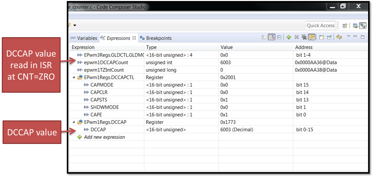
It seems that the register EPwm2Regs.DCCAP samples always 1, even if the comparator is switching (low to high) @ greater Ton.

Could you please tell me where is the error?

If the blanking is disabled (actually I would't need blanking to measure the Ton), the input of the 'AND' gate in the figure is always one or always 0?

Thank you in advance.

  • Good morning Nima,

    thank you for your suggestion. Actually I control those examples, but none of them uses the DCCAP register of the Digital Compare Submodule, to capture a PWM time base on DCEVTFILT. Understand how to do this is my problem.

    From manual I see a lot of signal entering in the Capture Control Logic, but it is not clear how do they trigger the capture action.

    Plese let me know if you have an example where you use the DCCAP register to capture a PWM time base.

    Thank you very much,

    Andrea Marcianesi.

  • I will work on an example specifically for this. I will post the code for you after I test it on my f28379d launchpad

  • Hi,

    Nima, that would be great!!!!

    Thank you very much.

    Regards,

    Andrea.

  • Here is an example for DCCAP DCCAPCTL.

    EPWM1 is setup for:

    TBPRD = 12000

    TB COUNTER MODE = UP/DOWN

    CHA: TZ forces it low when a DC event is present (DCAEVT)

    CHB: TZ forces it low after the blanking window (TBCTR=6000) using the DCBEVT which is source from the DCFILT

    DCFILT is passed to the DCCAP module to capture when the Trip occurs. Obvously no values less than 6000 because the blanking window will block the signal.

    The trip signal comes from GPIO 25, which is HIGH except for TBCTR counting UP and between 1000<CTR<7000.

    Here are the results and the code:

    //#############################################################################
    //
    // FILE:   epwm_ex11_digital_compare_event_capture_counter.c
    //
    // TITLE:  ePWM Using Digital Compare Submodule with
    //         Event Filter (Blanking Window) and the DCCAP
    //         (counter capture module).
    //
    //! \addtogroup driver_example_list
    //! <h1>ePWM Digital Compare Event Filter Counter Capture</h1>
    //!
    //! This example configures ePWM1 as follows
    //!  - ePWM1 with DCAEVT1 forcing the ePWM output LOW
    //!  - GPIO25 is used as the input to the INPUT XBAR INPUT1
    //!  - INPUT1 (from INPUT XBAR) is used as the source for DCAEVT1
    //!
    //!  - ePWM1 with DCBEVT1 forcing the ePWM output LOW
    //!  - GPIO25 is used as the input to the INPUT XBAR INPUT1
    //!  - INPUT1 (from INPUT XBAR) is used as the source for DCAEVT1
    //!  - GPIO25 is set to output mode and will trip the EPWM at specific timing
    //!  - DCBEVT1 uses the filtered version of DCBEVT1
    //!  - The DCFILT signal uses the blanking window to ignore the DCBEVT1
    //!    for the duration of DC Blanking window
    //!  - The DCCAP module will capture the DCFILT event's time of occurance
    //!
    //! \b External \b Connections \n
    //! - GPIO0 EPWM1A
    //! - GPIO1 EPWM1B
    //! - GPIO25 TRIPIN1, GPIO OUTPUT
    //!
    //! \b Watch \b Variables \n
    //! - None.
    //
    //
    //#############################################################################
    // $TI Release: F2837xD Support Library v3.06.00.00 $
    // $Release Date: Mon May 27 06:48:24 CDT 2019 $
    // $Copyright:
    // Copyright (C) 2013-2019 Texas Instruments Incorporated - http://www.ti.com/
    //
    // Redistribution and use in source and binary forms, with or without 
    // modification, are permitted provided that the following conditions 
    // are met:
    // 
    //   Redistributions of source code must retain the above copyright 
    //   notice, this list of conditions and the following disclaimer.
    // 
    //   Redistributions in binary form must reproduce the above copyright
    //   notice, this list of conditions and the following disclaimer in the 
    //   documentation and/or other materials provided with the   
    //   distribution.
    // 
    //   Neither the name of Texas Instruments Incorporated nor the names of
    //   its contributors may be used to endorse or promote products derived
    //   from this software without specific prior written permission.
    // 
    // THIS SOFTWARE IS PROVIDED BY THE COPYRIGHT HOLDERS AND CONTRIBUTORS 
    // "AS IS" AND ANY EXPRESS OR IMPLIED WARRANTIES, INCLUDING, BUT NOT 
    // LIMITED TO, THE IMPLIED WARRANTIES OF MERCHANTABILITY AND FITNESS FOR
    // A PARTICULAR PURPOSE ARE DISCLAIMED. IN NO EVENT SHALL THE COPYRIGHT 
    // OWNER OR CONTRIBUTORS BE LIABLE FOR ANY DIRECT, INDIRECT, INCIDENTAL, 
    // SPECIAL, EXEMPLARY, OR CONSEQUENTIAL DAMAGES (INCLUDING, BUT NOT 
    // LIMITED TO, PROCUREMENT OF SUBSTITUTE GOODS OR SERVICES; LOSS OF USE,
    // DATA, OR PROFITS; OR BUSINESS INTERRUPTION) HOWEVER CAUSED AND ON ANY
    // THEORY OF LIABILITY, WHETHER IN CONTRACT, STRICT LIABILITY, OR TORT 
    // (INCLUDING NEGLIGENCE OR OTHERWISE) ARISING IN ANY WAY OUT OF THE USE 
    // OF THIS SOFTWARE, EVEN IF ADVISED OF THE POSSIBILITY OF SUCH DAMAGE.
    // $
    //#############################################################################
    
    //
    // Included Files
    //
    #include "driverlib.h"
    #include "device.h"
    
    //
    // Globals
    //
    uint32_t  epwm1TZIntCount;
    volatile uint16_t  epwm1DCCAPCount;
    
    //
    // Function Prototypes
    //
    void initEPWM1(void);
    void initTZGPIO(void);
    void initEPWMGPIO(void);
    __interrupt void epwm1TZISR(void);
    __interrupt void epwm1ISR(void);
    
    void main(void)
    {
        //
        // Initialize global variables
        //
        epwm1TZIntCount = 0U;
        epwm1DCCAPCount = 0U;
    
        //
        // Initialize device clock and peripherals
        //
        Device_init();
    
        //
        // Disable pin locks and enable internal pull-ups.
        //
        Device_initGPIO();
    
        //
        // Initialize PIE and clear PIE registers. Disables CPU interrupts.
        //
        Interrupt_initModule();
    
        //
        // Initialize the PIE vector table with pointers to the shell Interrupt
        // Service Routines (ISR).
        //
        Interrupt_initVectorTable();
    
        //
        // Interrupts that are used in this example are re-mapped to ISR functions
        // found within this file.
        //
        Interrupt_register(INT_EPWM1, &epwm1ISR);
        //Interrupt_register(INT_EPWM1_TZ, &epwm1TZISR);
    
        //
        // Configure ePWM1, and TZ GPIOs
        //
        initEPWMGPIO();
        initTZGPIO();
    
        //
        // Disable sync(Freeze clock to PWM as well)
        //
        SysCtl_disablePeripheral(SYSCTL_PERIPH_CLK_GTBCLKSYNC);
        SysCtl_disablePeripheral(SYSCTL_PERIPH_CLK_TBCLKSYNC);
    
        //
        // Initialize ePWM1 with Digital Compare and Blanking window
        //
        initEPWM1();
    
        //
        // Enable sync and clock to PWM
        //
        SysCtl_enablePeripheral(SYSCTL_PERIPH_CLK_TBCLKSYNC);
    
        //
        // Enable interrupts required for this example
        //
        //Interrupt_enable(INT_EPWM1_TZ);
        Interrupt_enable(INT_EPWM1);
    
        //
        // Enable Global Interrupt (INTM) and real time interrupt (DBGM)
        //
        EINT;
        ERTM;
    
        //
        // IDLE loop. Just sit and loop forever (optional):
        //
        for(;;)
        {
            if ((EPWM_TIME_BASE_STATUS_COUNT_UP ==
                    EPWM_getTimeBaseCounterDirection(EPWM1_BASE)) &&
                (EPWM_getTimeBaseCounterValue(EPWM1_BASE) > 1000 &&
                        EPWM_getTimeBaseCounterValue(EPWM1_BASE) < 7000))
            {
                GPIO_writePin(25, 0);
            }
            else
            {
                GPIO_writePin(25, 1);
            }
            NOP;
        }
    }
    
    //
    // epwm1ISR - ePWM 1 ISR
    //
    __interrupt void epwm1ISR(void)
    {
    
        epwm1DCCAPCount = EPWM_getDigitalCompareCaptureCount(EPWM1_BASE);
        //
        // Clear INT flag for this timer
        //
        EPWM_clearEventTriggerInterruptFlag(EPWM1_BASE);
    
        //
        // Acknowledge interrupt group
        //
        Interrupt_clearACKGroup(INTERRUPT_ACK_GROUP3);
    }
    
    
    //
    // epwm1TZISR - ePWM1 TZ ISR
    //
    //__interrupt void epwm1TZISR(void)
    //{
    //    epwm1TZIntCount++;
    //
    //    //
    //    // To re-enable the Interrupts
    //    //
    //    EPWM_clearTripZoneFlag(EPWM1_BASE,
    //                           EPWM_TZ_FLAG_DCAEVT1 | EPWM_TZ_FLAG_DCBEVT1 | EPWM_TZ_INTERRUPT);
    //
    //    //
    //    // Acknowledge this interrupt to receive more interrupts from group 2
    //    //
    //    Interrupt_clearACKGroup(INTERRUPT_ACK_GROUP2);
    //}
    
    //
    // initEPWM1 - Configure ePWM1
    //
    void initEPWM1()
    {
        EPWM_setEmulationMode(EPWM1_BASE, EPWM_EMULATION_STOP_AFTER_NEXT_TB);
        //
        // Select TRIPIN1 (INPUT XBAR INPUT1) as the source for DCAH
        //
        EPWM_selectDigitalCompareTripInput(
                EPWM1_BASE, EPWM_DC_TRIP_TRIPIN1, EPWM_DC_TYPE_DCAH);
    
        //
        // DCAEVT1 is generated when DCAH is low
        //
        EPWM_setTripZoneDigitalCompareEventCondition(
                EPWM1_BASE, EPWM_TZ_DC_OUTPUT_A1, EPWM_TZ_EVENT_DCXH_LOW);
    
        //
        // DCAEVT1 uses the unfiltered version of DCAEVT1
        //
        EPWM_setDigitalCompareEventSource(
                EPWM1_BASE, EPWM_DC_MODULE_A, EPWM_DC_EVENT_1, EPWM_DC_EVENT_SOURCE_ORIG_SIGNAL);
    
        //
        // DCAEVT1 is asynchronous
        //
        EPWM_setDigitalCompareEventSyncMode(
                EPWM1_BASE, EPWM_DC_MODULE_A, EPWM_DC_EVENT_1, EPWM_DC_EVENT_INPUT_NOT_SYNCED);
    
        //
        // Select TRIPIN1 (INPUT XBAR INPUT1) as the source for DCBH
        //
        EPWM_selectDigitalCompareTripInput(
                EPWM1_BASE, EPWM_DC_TRIP_TRIPIN1, EPWM_DC_TYPE_DCBH);
        //
        // DCBEVT1 is generated when DCBH is low
        //
        EPWM_setTripZoneDigitalCompareEventCondition(
                EPWM1_BASE, EPWM_TZ_DC_OUTPUT_B1, EPWM_TZ_EVENT_DCXH_LOW);
    
        //
        // DCBEVT1 as input for DCFILT
        //
        EPWM_setDigitalCompareFilterInput(
                EPWM1_BASE, EPWM_DC_WINDOW_SOURCE_DCBEVT1);
    
        //
        // DCFILT do not invert
        //
        EPWM_disableDigitalCompareWindowInverseMode(EPWM1_BASE);
    
        //
        // Blanking window start at CTR=0
        //
        EPWM_setDigitalCompareBlankingEvent(EPWM1_BASE, EPWM_DC_WINDOW_START_TBCTR_ZERO);
    
        //
        // Blanking window period set to 6000
        //
        EPWM_setDigitalCompareWindowLength(EPWM1_BASE, 6000U);
    
        //
        // Blanking window starts at CTR=0 without any offset
        //
        EPWM_setDigitalCompareWindowOffset(EPWM1_BASE, 0);
    
        //
        // Blanking window enabled
        //
        EPWM_enableDigitalCompareBlankingWindow(EPWM1_BASE);
    
        //
        // DCBEVT1 is the DCFILT input
        //
        EPWM_setDigitalCompareEventSource(
                EPWM1_BASE, EPWM_DC_MODULE_B, EPWM_DC_EVENT_1, EPWM_DC_EVENT_SOURCE_FILT_SIGNAL);
    
        //
        // DCBEVT1 is asynchronous
        //
        EPWM_setDigitalCompareEventSyncMode(
                EPWM1_BASE, EPWM_DC_MODULE_B, EPWM_DC_EVENT_1, EPWM_DC_EVENT_INPUT_NOT_SYNCED);
    
    
        //
        // Action on DCAEVT1
        //
        EPWM_setTripZoneAction(EPWM1_BASE,
                               EPWM_TZ_ACTION_EVENT_DCAEVT1,
                               EPWM_TZ_ACTION_LOW);
    
        //
        // Action on DCBEVT1
        //
        EPWM_setTripZoneAction(EPWM1_BASE,
                               EPWM_TZ_ACTION_EVENT_DCBEVT1,
                               EPWM_TZ_ACTION_LOW);
    
        //
        // Use shadow mode for the DCCAP
        //
        EPWM_setDigitalCompareCounterShadowMode(EPWM1_BASE, true);
    
        //
        // Enable the Counter Capture
        //
        EPWM_enableDigitalCompareCounterCapture(EPWM1_BASE);
    
        //
        // Enable TZ interrupt
        //
        //EPWM_enableTripZoneInterrupt(EPWM1_BASE, EPWM_TZ_INTERRUPT_DCAEVT1);
    
        //
        // Set-up TBCLK
        //
        EPWM_setTimeBasePeriod(EPWM1_BASE, 12000U);
        EPWM_setPhaseShift(EPWM1_BASE, 0U);
        EPWM_setTimeBaseCounter(EPWM1_BASE, 0U);
        EPWM_setTimeBaseCounterMode(EPWM1_BASE, EPWM_COUNTER_MODE_UP_DOWN);
        EPWM_disablePhaseShiftLoad(EPWM1_BASE);
    
        //
        // Set ePWM clock pre-scaler
        //
        EPWM_setClockPrescaler(EPWM1_BASE,
                               EPWM_CLOCK_DIVIDER_4,
                               EPWM_HSCLOCK_DIVIDER_4);
    
        //
        // Set up shadowing
        //
        EPWM_setCounterCompareShadowLoadMode(EPWM1_BASE,
                                             EPWM_COUNTER_COMPARE_A,
                                             EPWM_COMP_LOAD_ON_CNTR_ZERO);
    
        //
        // Set-up compare
        //
        EPWM_setCounterCompareValue(EPWM1_BASE, EPWM_COUNTER_COMPARE_A, 2000U);
    
        //
        // Set actions
        //
        EPWM_setActionQualifierAction(EPWM1_BASE,
                                      EPWM_AQ_OUTPUT_A,
                                      EPWM_AQ_OUTPUT_HIGH,
                                      EPWM_AQ_OUTPUT_ON_TIMEBASE_UP_CMPA);
        EPWM_setActionQualifierAction(EPWM1_BASE,
                                      EPWM_AQ_OUTPUT_A,
                                      EPWM_AQ_OUTPUT_LOW,
                                      EPWM_AQ_OUTPUT_ON_TIMEBASE_DOWN_CMPA);
        EPWM_setActionQualifierAction(EPWM1_BASE,
                                      EPWM_AQ_OUTPUT_B,
                                      EPWM_AQ_OUTPUT_HIGH,
                                      EPWM_AQ_OUTPUT_ON_TIMEBASE_UP_CMPA);
        EPWM_setActionQualifierAction(EPWM1_BASE,
                                      EPWM_AQ_OUTPUT_B,
                                      EPWM_AQ_OUTPUT_LOW,
                                      EPWM_AQ_OUTPUT_ON_TIMEBASE_DOWN_CMPA);
    
        //
        // Interrupt where we will change the Compare Values
        // Select INT on Time base counter zero event,
        // Enable INT, generate INT on 1rd event
        //
        EPWM_setInterruptSource(EPWM1_BASE, EPWM_INT_TBCTR_ZERO);
        EPWM_enableInterrupt(EPWM1_BASE);
        EPWM_setInterruptEventCount(EPWM1_BASE, 1U);
    }
    
    //
    // initTZGPIO - Configure TZ GPIO
    //
    void initTZGPIO(void)
    {
        //
        // Set GPIO 25 as as Asynchronous input with pull up enabled
        //
        GPIO_setPadConfig(25, GPIO_PIN_TYPE_STD);
        GPIO_setPinConfig(GPIO_25_GPIO25);
        GPIO_setDirectionMode(25, GPIO_DIR_MODE_OUT);
    
        GPIO_writePin(25, 1);
        //
        // Set GPIO 25 as TZ1 input
        //
        XBAR_setInputPin(XBAR_INPUT1, 25);
    
    }
    
    //
    // initEPWMGPIO - Configure ePWM GPIO
    //
    void initEPWMGPIO(void)
    {
        //
        // Disable pull up on GPIO 0 configure them as PWM1A
        //
        GPIO_setPadConfig(0, GPIO_PIN_TYPE_STD);
        GPIO_setPinConfig(GPIO_0_EPWM1A);
    
        //
        // Disable pull up on GPIO 0 configure them as PWM1A
        //
        GPIO_setPadConfig(1, GPIO_PIN_TYPE_STD);
        GPIO_setPinConfig(GPIO_1_EPWM1B);
    
    }