This thread has been locked.

If you have a related question, please click the "Ask a related question" button in the top right corner. The newly created question will be automatically linked to this question.

TMS320F28035: Cannot clear INTCNT bit[3-2] in Event-Trigger Prescale Register (ETPS)

Part Number: TMS320F28035


Hi,All:

I read the Technical Reference Manual of tms320f28035(SPRUI10–December 2018) , and in In Chapter 3.2.8 (page275), it says :

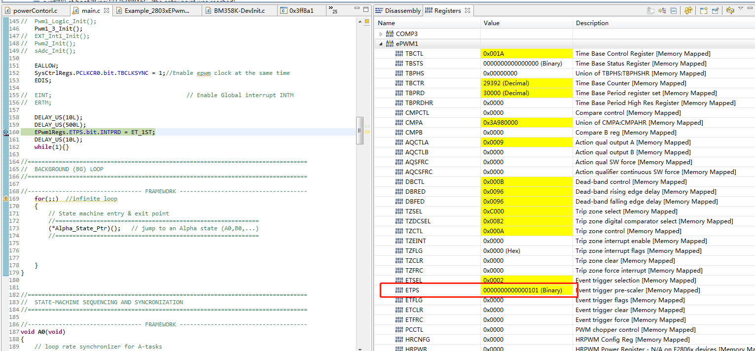
In my code, ET init config :


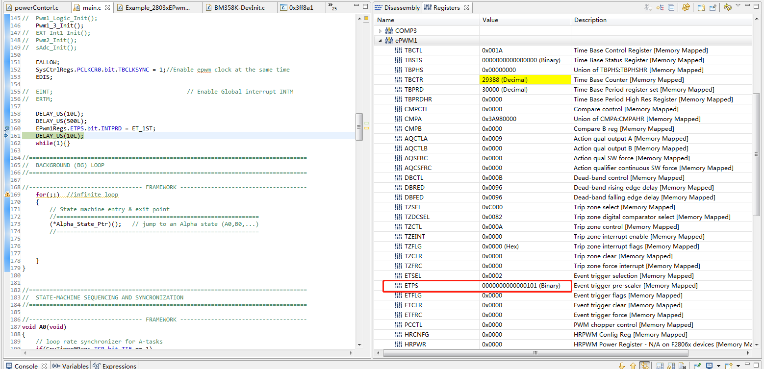
It can be seen that i generate INT on every 1st event, about 20ms later, befor i enable the interrupt of the ET,  I noticed that  INTCNT bit[3-2]  == 01(binary), then i reassign the INTPRD bit[1-0] = 11(binary), 

But it did not empty the INTCNT bit[3-2], why?

Thanks for help.

  • Solider 76,

    sorry for the slow reply, is it possible that you are setting INTPRD just before a another interrupt pulse comes in?

    Also if you are using breakpoints and single steps then the PWM's emulation mode bits could also explain this issue. Depending on the value found in bits [15:14] of the TBCTL register the behavior of the ePWM will change after an emulation event. For example if it was set to "01" INTPRD could increment even if the breakpoint occurred before the end of period.

    Regards,
    Cody 

  • Thanks for your reply, 

    bits [15:14] of the TBCTL register is a default value 0.

    I streamlined the code and it only have epwm1 module and DELAY_US() function,In addition, I blocked the global interruption.

    as you can see two picture below, after execute <EPwm1Regs.ETPS.bit.INTPRD = ET_1ST;>, The ETPS value changes nothing.

    void main(void)
    {

    // Only used if running from FLASH
    // Note that the variable FLASH is defined by the compiler with -d FLASH
    #ifdef FLASH
    // Copy time critical code and Flash setup code to RAM
    // The RamfuncsLoadStart, RamfuncsLoadEnd, and RamfuncsRunStart
    // symbols are created by the linker. Refer to the linker files.
    memcpy((uint16_t *)&RamfuncsRunStart,(uint16_t *)&RamfuncsLoadStart,
    (unsigned long)&RamfuncsLoadSize);

    // Call Flash Initialization to setup flash waitstates
    // This function must reside in RAM
    InitFlash(); // Call the flash wrapper init function
    #endif //(FLASH)


    Device_Init();
    //
    //// Timing sync for background loops
    //// Timer period definitions found in PeripheralHeaderIncludes.h
    // CpuTimer0Regs.PRD.all = mSec1; // A tasks
    // CpuTimer1Regs.PRD.all = mSec5; // B tasks
    // CpuTimer2Regs.PRD.all = mSec100; // C tasks
    //
    //// Tasks State-machine init
    // Alpha_State_Ptr = &A0;
    // A_Task_Ptr = &A1;
    // B_Task_Ptr = &B1;
    // C_Task_Ptr = &C1;
    //
    // VTimer0[0] = 0;
    // VTimer1[0] = 0;
    // VTimer2[0] = 0;
    // LedBlinkCnt = 5;

    DELAY_US(9000L);


    // Pwm1_Logic_Init();
    Pwm1_3_Init();
    // EXT_Int1_Init();
    // Pwm2_Init();
    // sAdc_Init();

    EALLOW;
    SysCtrlRegs.PCLKCR0.bit.TBCLKSYNC = 1;//Enable epwm clock at the same time
    EDIS;

    // EINT; // Enable Global interrupt INTM
    // ERTM;

    DELAY_US(10L);
    DELAY_US(500L);
    EPwm1Regs.ETPS.bit.INTPRD = ET_1ST;
    DELAY_US(10L);
    while(1){}

    }

    ----------------------------------------------------------------------------

    void Pwm1_3_Init(void)
    {
    /*********************************************************
    //pwm1 and pwm3 are configed in the same frequency, period.
    //except (EPwm1Regs.TBCTL.bit.PHSEN) is not same
    //pwm3 use its tz interrupt to record pwm1 ctr register to calculate driver delay, and record the count of pan detected pulse
    **********************************************************/

    //--------------------------------------------------
    //pwm1
    //---------------------------------------------------
    wPWM1Freq = 1000; // init Freq
    wPWM1Period = (Uint16)(60000000 / wPWM1Freq);


    EPwm1Regs.TBCTL.bit.PRDLD = TB_IMMEDIATE;//TB_SHADOW; // set load on CTR=0

    EPwm1Regs.TBPRD = wPWM1Period / 2; // PWM frequency = 1 / period
    EPwm1Regs.TBPHS.half.TBPHS = 0x0000; // Phase is 0
    EPwm1Regs.TBCTR = 0x0000; // Clear counter

    // Setup TBCLK
    EPwm1Regs.TBCTL.bit.CTRMODE = TB_COUNT_UPDOWN; // Count updown
    EPwm1Regs.TBCTL.bit.PHSEN = TB_DISABLE; // Disable phase loading
    // EPwm1Regs.TBCTL.bit.PRDLD = TB_SHADOW; // set load on CTR=0
    EPwm1Regs.TBCTL.bit.SYNCOSEL = TB_CTR_ZERO; // Sync down-stream module
    EPwm1Regs.TBCTL.bit.HSPCLKDIV = 0; // Clock ratio to SYSCLKOUT
    EPwm1Regs.TBCTL.bit.CLKDIV = 0; // Slow so we can observe on the scope

    //EPwm1Regs.TBCTL.bit.FREE_SOFT = 11; // XYN, Emulation Mode Bits 1X FREE RUN

    // Setup compare
    EPwm1Regs.CMPA.half.CMPA = wPWM1Period / 4;
    EPwm1Regs.CMPCTL.bit.SHDWAMODE = CC_SHADOW;
    EPwm1Regs.CMPCTL.bit.LOADAMODE = CC_CTR_ZERO; // load on CTR=Zero

    // // Set actions
    // EPwm1Regs.AQCTLA.bit.ZRO = AQ_SET; // Set
    // EPwm1Regs.AQCTLA.bit.PRD = AQ_CLEAR; // Clear

    // Set actions
    EPwm1Regs.AQCTLA.bit.ZRO = AQ_CLEAR;
    EPwm1Regs.AQCTLA.bit.PRD = AQ_SET;

    // Active high complementary PWMs - Setup the deadband
    EPwm1Regs.DBCTL.bit.OUT_MODE = DB_FULL_ENABLE;
    EPwm1Regs.DBCTL.bit.POLSEL = DB_ACTV_HIC;
    EPwm1Regs.DBCTL.bit.IN_MODE = DBA_ALL;
    EPwm1Regs.DBRED = DB_2_5us;
    EPwm1Regs.DBFED = DB_2_5us;

    //config pwm1 isr
    //isr purpose:
    //1. turn off pwm1 output, this lead to a detected pulse
    //2. after some time ,turn off the isr, set the end of pan detect flag EOPD
    EALLOW;
    PieVectTable.EPWM1_INT = &EPWM1_INT_ISR; // Map PWM Interrupt
    PieCtrlRegs.PIEIER3.bit.INTx1 = 1; // PIE level enable, Grp3 / Int1, ePWM1
    EDIS;

    EPwm1Regs.ETSEL.bit.INTSEL = ET_CTR_PRD; // INT on Counter-Zero event
    EPwm1Regs.ETSEL.bit.INTEN = 0; // Disable INT
    EPwm1Regs.ETPS.bit.INTPRD = ET_1ST; // Generate INT on every 1st event


    IER |= M_INT3; // Enable CPU INT3 connected to EPWM1-6 INTs:


    // EINT; // Enable Global interrupt INTM
    // ERTM; // Enable Global realtime interrupt DBGM

    //--------------------------------------------------
    //comp1 2
    //---------------------------------------------------
    //comp1 as a up half current limit
    //comp2 as a down half current limit
    //if current in not overcurrent, output of pin i/o should be low
    EALLOW;
    // Configure Analog Comparators
    Comp1Regs.COMPCTL.bit.SYNCSEL = 1; // Sync with SYSCLK / use Qualification
    Comp1Regs.COMPCTL.bit.QUALSEL = 3; // Require input be stable for 3 consecutive SYSCLKs
    Comp1Regs.COMPCTL.bit.CMPINV = 0; // Output Low when true
    Comp1Regs.COMPCTL.bit.COMPSOURCE = 0; // Use internal DAC
    Comp1Regs.COMPCTL.bit.COMPDACEN = 1; // Enable DAC
    Comp1Regs.DACVAL.bit.DACVAL = 821;//COMP1; // Trip Current = DACVAL/1023*82.5


    Comp2Regs.COMPCTL.bit.SYNCSEL = 1; // Sync with SYSCLK / use Qualification
    Comp2Regs.COMPCTL.bit.QUALSEL = 3; // Require input be stable for 3 consecutive SYSCLKs
    Comp2Regs.COMPCTL.bit.CMPINV = 1; // Output Low when true
    Comp2Regs.COMPCTL.bit.COMPSOURCE = 0; // Use internal DAC
    Comp2Regs.COMPCTL.bit.COMPDACEN = 1; // Enable DAC
    Comp2Regs.DACVAL.bit.DACVAL = 202;//COMP2; // Trip Current = DACVAL/1023*82.5


    // Define an event (DCAEVT1) based on TZ1 and TZ2
    EPwm1Regs.DCTRIPSEL.bit.DCAHCOMPSEL = DC_COMP1OUT; // DCAH = Comparator 1 output
    //EPwm1Regs.DCTRIPSEL.bit.DCALCOMPSEL = DC_TZ2; // DCAL = TZ2
    EPwm1Regs.TZDCSEL.bit.DCAEVT1 = TZ_DCAH_HI; // DCAEVT1 = DCAH low(will become active as Comparator output goes low)
    EPwm1Regs.DCACTL.bit.EVT1SRCSEL = DC_EVT1; // DCAEVT1 = DCAEVT1 (not filtered)
    EPwm1Regs.DCACTL.bit.EVT1FRCSYNCSEL = DC_EVT_ASYNC; // Take async path

    // Define an event (DCBEVT1) based on TZ1 and TZ2
    EPwm1Regs.DCTRIPSEL.bit.DCBHCOMPSEL = DC_COMP2OUT; // DCBH = Comparator 1 output
    //EPwm1Regs.DCTRIPSEL.bit.DCBLCOMPSEL = DC_TZ2; // DCAL = TZ2
    EPwm1Regs.TZDCSEL.bit.DCBEVT1 = TZ_DCBH_HI; // DCBEVT1 = (will become active as Comparator output goes low)
    EPwm1Regs.DCBCTL.bit.EVT1SRCSEL = DC_EVT1; // DCBEVT1 = DCBEVT1 (not filtered)
    EPwm1Regs.DCBCTL.bit.EVT1FRCSYNCSEL = DC_EVT_ASYNC; // Take async path

    // Enable DCAEVT1 and DCBEVT1 are one shot trip sources
    // Note: DCxEVT1 events can be defined as one-shot.
    // DCxEVT2 events can be defined as cycle-by-cycle.
    EPwm1Regs.TZSEL.bit.DCAEVT1 = 1;
    EPwm1Regs.TZSEL.bit.DCBEVT1 = 1;

    // What do we want the DCAEVT1 and DCBEVT1 events to do?
    // DCAEVTx events can force EPWMxA
    // DCBEVTx events can force EPWMxB
    EPwm1Regs.TZCTL.bit.TZA = TZ_FORCE_LO; // EPWM1A will go high
    EPwm1Regs.TZCTL.bit.TZB = TZ_FORCE_LO; // EPWM1B will go low

    EDIS;


    //--------------------------------------------------
    //comp3
    //---------------------------------------------------
    EALLOW;
    // Configure Analog Comparators
    Comp3Regs.COMPCTL.bit.SYNCSEL = 1; // Sync with SYSCLK / use Qualification
    Comp3Regs.COMPCTL.bit.QUALSEL = 3; // Require input be stable for 3 consecutive SYSCLKs
    Comp3Regs.COMPCTL.bit.CMPINV = 0; // Output Low when true
    Comp3Regs.COMPCTL.bit.COMPSOURCE = 0; // Use internal DAC
    Comp3Regs.COMPCTL.bit.COMPDACEN = 1; // Enable DAC
    Comp3Regs.DACVAL.bit.DACVAL = 496; //
    EDIS;


    // EINT; // Enable Global interrupt INTM
    // ERTM;

    }

    ------------------------------------------------

    #define DELAY_US(A)  DSP28x_usDelay(((((long double) A * 1000.0L) / (long double)CPU_RATE) - 9.0L) / 5.0L)

  • Could you please try the same experiment with your interrupt period set to 2 and 3?

    Are you changing INTPRD from a non-1 value to 1, or INTPRD=1 before you write a 1?

    Thanks,
    Cody 

  • Hi,Cody

    I did what you said, but the problem still exists. 

    Attachment is my project code, could please check it for me?HB-et2.zip.rar

  • Edited for correctness.

    Soldier 76,

    Looking into this it appears that the counter clears when writing an INTPRD value equal to INTCNT or equal to 0. If you write INTPRD = INTCNT it will trigger an interrupt. For example INTCNT =2 you can reset this by writing 0 or 2 into INTPRD. Writing a 3 or a 1 will not reset INTCNT.

    If INTCNT =1 and INTPRD =2 setting INTPRD = 3 will not reset INTCNT.

    If you want the count to always be reset when adjusting INTPRD then write INTPRD = 0 and then INTPRD = 'desired value'.

    Hope it helps.

    Regards,
    Cody