This thread has been locked.

If you have a related question, please click the "Ask a related question" button in the top right corner. The newly created question will be automatically linked to this question.

CCS: phase shift between ePWMA and ePWMB

Tool/software: Code Composer Studio

Hi TI Community,

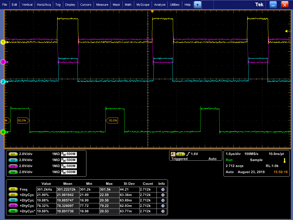
i try here to shifting my two PWMs (ePWM1A and ePWM1B) with 180 degree, i used your example of epwm _synchronization, and i got a shift between two ePWMs for example ePWM1 and ePWM2. and now how cana i get a shift for ePWMA and ePWMB and not an inverted signal. 

Thank you!

here is my initEPWM1:

void initEPWM1_Configuration(void)
{
EPWM_setClockPrescaler(EPWM1_BASE,
EPWM_CLOCK_DIVIDER_1,
EPWM_HSCLOCK_DIVIDER_1);
//
EPWM_setTimeBaseCounterMode(EPWM1_BASE, EPWM_COUNTER_MODE_UP);
EPWM_setTimeBaseCounter(EPWM1_BASE, 0);// count initial value setting
EPWM_setTimeBasePeriod(EPWM1_BASE, EPWM_TIMER_TBPRD); //count cycle fs=300khz
//
EPWM_setPeriodLoadMode(EPWM1_BASE, EPWM_PERIOD_SHADOW_LOAD);// CYCLE LOADING MODE
EPWM_setCounterCompareShadowLoadMode(EPWM1_BASE,
EPWM_COUNTER_COMPARE_A,
EPWM_COMP_LOAD_ON_CNTR_ZERO_PERIOD); // comparison value loading mode
EPWM_setCounterCompareShadowLoadMode(EPWM1_BASE,
EPWM_COUNTER_COMPARE_B,
EPWM_COMP_LOAD_ON_CNTR_ZERO_PERIOD);

EPWM_setCounterCompareValue(EPWM1_BASE, EPWM_COUNTER_COMPARE_A, Duty_cycle); //Set the comparison value
EPWM_setCounterCompareValue(EPWM1_BASE, EPWM_COUNTER_COMPARE_B, Duty_cycle);
//
EPWM_setActionQualifierAction(EPWM1_BASE,
EPWM_AQ_OUTPUT_A,
EPWM_AQ_OUTPUT_LOW,
EPWM_AQ_OUTPUT_ON_TIMEBASE_UP_CMPA); //ePWMA
//
EPWM_setActionQualifierAction(EPWM1_BASE,
EPWM_AQ_OUTPUT_A,
EPWM_AQ_OUTPUT_HIGH,
EPWM_AQ_OUTPUT_ON_TIMEBASE_PERIOD);
EPWM_setActionQualifierAction(EPWM1_BASE,
EPWM_AQ_OUTPUT_B,
EPWM_AQ_OUTPUT_LOW,
EPWM_AQ_OUTPUT_ON_TIMEBASE_UP_CMPA); //ePWMA
//
EPWM_setActionQualifierAction(EPWM1_BASE,
EPWM_AQ_OUTPUT_B,
EPWM_AQ_OUTPUT_HIGH,
EPWM_AQ_OUTPUT_ON_TIMEBASE_PERIOD);
//
EPWM_setSyncOutPulseMode(EPWM1_BASE, EPWM_SYNC_OUT_PULSE_ON_COUNTER_ZERO); //Synchronize pulse when counting to zero
//
EPWM_setRisingEdgeDeadBandDelayInput(EPWM1_BASE,EPWM_DB_INPUT_EPWMA);
EPWM_setFallingEdgeDeadBandDelayInput(EPWM1_BASE, EPWM_DB_INPUT_EPWMA); //Configure dead zone input mode
EPWM_setDeadBandDelayPolarity(EPWM1_BASE,EPWM_DB_RED,EPWM_DB_POLARITY_ACTIVE_HIGH);
EPWM_setDeadBandDelayPolarity(EPWM1_BASE, EPWM_DB_FED, EPWM_DB_POLARITY_ACTIVE_HIGH); // configuration polarity
EPWM_setDeadBandDelayMode(EPWM1_BASE,EPWM_DB_RED,true);
EPWM_setDeadBandDelayMode(EPWM1_BASE, EPWM_DB_FED, true); //Configure output mode
EPWM_setDeadBandOutputSwapMode(EPWM1_BASE,EPWM_DB_OUTPUT_A,false);
EPWM_setDeadBandOutputSwapMode(EPWM1_BASE, EPWM_DB_OUTPUT_B, false); //Output is not exchanged
//
EPWM_setRisingEdgeDelayCount(EPWM1_BASE, Dead_Band_RED); //Rising edge delay 0nS
EPWM_setFallingEdgeDelayCount(EPWM1_BASE, Dead_Band_FED); //falling edge delay 0nS
}

  • The C28x uses a modular PWM architecture; each module producing two PWM outputs (A and B) from the same time-base.  The hardware phase shift mechanism allows the user to adjust the offset between time-bases of separate PWM modules.  If you want to create phase shift between PWM patterns on A & B outputs on the same module, you will have to set up the Counter Compare (CC) and Acquisition Qualifier (AQ) sub-modules in your code to do this.  It will be challenging in up-count mode, but in up-down count mode you could do something like in the attachment.

    BTW, there is a video on PWM architecture which you may find helpful, here:

    https://training.ti.com/getting-started-c2000-epwm-module?keyMatch=ePWM&tisearch=Search-EN-Everything

    Regards,

    Richard

    ePWM waveform example.pdf

  • Hi Richard, 

    i followed your tips, i still have difficulties to determine the duty-cycle for example 20%, the time-base period is 2000. the settings for SetAction are as right as below!
    Thank you

    // Set-up compare
    EPWM_setCounterCompareValue(base, EPWM_COUNTER_COMPARE_A, 400U); // need Duty-cycle of 20%
    EPWM_setCounterCompareValue(base, EPWM_COUNTER_COMPARE_B, (EPWM_TIMER_TBPRD-400U)); // need Duty-cycle of 20%
    // Set actions
    /*EPWM_setActionQualifierAction(base,
    EPWM_AQ_OUTPUT_A,
    EPWM_AQ_OUTPUT_LOW,
    EPWM_AQ_OUTPUT_ON_TIMEBASE_ZERO);*/
    EPWM_setActionQualifierAction(base,
    EPWM_AQ_OUTPUT_A,
    EPWM_AQ_OUTPUT_HIGH,
    EPWM_AQ_OUTPUT_ON_TIMEBASE_UP_CMPA);
    /*EPWM_setActionQualifierAction(base,
    EPWM_AQ_OUTPUT_A,
    EPWM_AQ_OUTPUT_NO_CHANGE,
    EPWM_AQ_OUTPUT_ON_TIMEBASE_PERIOD);*/
    EPWM_setActionQualifierAction(base,
    EPWM_AQ_OUTPUT_A,
    EPWM_AQ_OUTPUT_LOW,
    EPWM_AQ_OUTPUT_ON_TIMEBASE_UP_CMPB);
    EPWM_setActionQualifierAction(base,
    EPWM_AQ_OUTPUT_B,
    EPWM_AQ_OUTPUT_LOW,
    EPWM_AQ_OUTPUT_ON_TIMEBASE_ZERO);
    EPWM_setActionQualifierAction(base,
    EPWM_AQ_OUTPUT_B,
    EPWM_AQ_OUTPUT_HIGH,
    EPWM_AQ_OUTPUT_ON_TIMEBASE_PERIOD);
    /* EPWM_setActionQualifierAction(base,
    EPWM_AQ_OUTPUT_B,
    EPWM_AQ_OUTPUT_NO_CHANGE,
    EPWM_AQ_OUTPUT_ON_TIMEBASE_PERIOD);*/
    EPWM_setActionQualifierAction(base,
    EPWM_AQ_OUTPUT_B,
    EPWM_AQ_OUTPUT_LOW,
    EPWM_AQ_OUTPUT_ON_TIMEBASE_DOWN_CMPB);

  • Assuming you have configured the counter in up-down mode, as I draw this out I think you're going to get 30% duty on output A and 10% on output B.  Is that right?

    You have output A going high on an up-count match of 400, and low on an up-count of 1600, so 1200 counts on a time-base of 4000 (remember, up-down mode will double the number of clock pulses in a PWM period). 1200/4000*100 = 30%.

    You have output B going high on a period event and low on down count match of 1600, so 400 counts. 400/4000*100 = 10%.  

    Start by drawing out the waveforms you want on the time-base, in a similar way to the .pdf I sent.  That should guide you towards the right AQ settings.

    What is the duty and phase relationship you're trying to get?

    Regards,

    Richard

  • Hi Richard,

    I try to get a phase shift of 180 degrees between the two, both should have the same duty cycle for example from 10% to 50%.

    with :

    // Set-up compare
    EPWM_setCounterCompareValue(base, EPWM_COUNTER_COMPARE_A, 400U); // need Duty-cycle of 20%
    EPWM_setCounterCompareValue(base, EPWM_COUNTER_COMPARE_B, (EPWM_TIMER_TBPRD-800U)); // need Duty-cycle of 20%

    i got for example 20% but but not the exact phase shift

    Regards

    YT

  • Since you're looking for a fixed 180 deg phase, this should be easy. What about something like this?

    // Set-up compare
    EPWM_setCounterCompareValue(base, EPWM_COUNTER_COMPARE_A, 800U); // need Duty-cycle of 20%
    EPWM_setCounterCompareValue(base, EPWM_COUNTER_COMPARE_B, (EPWM_TIMER_TBPRD-800U)); // need Duty-cycle of 20%

    // Set actions
    EPWM_setActionQualifierAction(base,
    EPWM_AQ_OUTPUT_A,
    EPWM_AQ_OUTPUT_HIGH,
    EPWM_AQ_OUTPUT_ON_TIMEBASE_ZERO);

    EPWM_setActionQualifierAction(base,
    EPWM_AQ_OUTPUT_A,
    EPWM_AQ_OUTPUT_LOW,
    EPWM_AQ_OUTPUT_ON_TIMEBASE_UP_CMPA);

    EPWM_setActionQualifierAction(base,
    EPWM_AQ_OUTPUT_B,
    EPWM_AQ_OUTPUT_HIGH,
    EPWM_AQ_OUTPUT_ON_TIMEBASE_PERIOD);

    EPWM_setActionQualifierAction(base,
    EPWM_AQ_OUTPUT_B,
    EPWM_AQ_OUTPUT_LOW,
    EPWM_AQ_OUTPUT_ON_TIMEBASE_DOWN_CMPB);

    Hope this helps.

    Regards,

    Richard

  • Thank you Richard ! I got it 

  • Hi Richard,

    i have another question, it's about the Dead Band settings, i have added the Dead Band setting to the upper code, but i don't get any phase shift anymore, i've tried to solve with the more times, you might have a solution ? Thank you

    Best Regards

    YT

    EPWM_setSyncOutPulseMode(EPWM1_BASE, EPWM_SYNC_OUT_PULSE_ON_COUNTER_ZERO); //Synchronize pulse when counting to zero
    //
    EPWM_setRisingEdgeDeadBandDelayInput(EPWM1_BASE,EPWM_DB_INPUT_EPWMA);
    EPWM_setFallingEdgeDeadBandDelayInput(EPWM1_BASE, EPWM_DB_INPUT_EPWMA); //Configure dead zone input mode
    EPWM_setDeadBandDelayPolarity(EPWM1_BASE,EPWM_DB_RED,EPWM_DB_POLARITY_ACTIVE_HIGH);
    EPWM_setDeadBandDelayPolarity(EPWM1_BASE, EPWM_DB_FED, EPWM_DB_POLARITY_ACTIVE_HIGH); // configuration polarity
    EPWM_setDeadBandDelayMode(EPWM1_BASE,EPWM_DB_RED,true);
    EPWM_setDeadBandDelayMode(EPWM1_BASE, EPWM_DB_FED, true); //Configure output mode
    EPWM_setDeadBandOutputSwapMode(EPWM1_BASE,EPWM_DB_OUTPUT_A,false);
    EPWM_setDeadBandOutputSwapMode(EPWM1_BASE, EPWM_DB_OUTPUT_B, false); //Output is not exchanged
    //
    EPWM_setRisingEdgeDelayCount(EPWM1_BASE, Dead_Band_RED); //Rising edge delay 3nS
    EPWM_setFallingEdgeDelayCount(EPWM1_BASE, Dead_Band_FED); //falling edge delay 3nS

  • Yes, that is correct. When you use the DB module it handles the complementary pair generation and inserts dead-band. FED mode is shown in figure 18-34 of this document:
    www.ti.com/.../sprui33c.pdf

    In the PWM module, you're either generating both A & B patterns by edge placement with the AQ sub-module, or generating one and configuring the DB module to produce the other.

    Why do you need dead-band? In the phase shifted pattern you described, none of the edges would be coincident unless the duty cycle reached 50%.

    Regards,

    Richard

  • I need it to avoid the short circuit between A and B when they both reach 50% of duty cycle, and also because I have two pwm 3B and 4B inverted to the other 1A and 1B, for the two 3B and 4B I already have a dead band, only missing on ePWM1A and 1B.

    Regards

    YT

  • Hi, 

    can you help about this:

    I have a problem with Dead Band on ePWM1B (yellow), if I get Dead Band for Rissing edge on ePWM1B I don't get 180 phase shift between ePWM1A (green) and 1B, so I only have Falling edge on ePWM1B, but I don't get desired Dead Band between 1B and 3A/3B (blue and purple). can you help me about this!

    Best Regards

    YT

    // Dead Band for ePWM1
    EPWM_setRisingEdgeDeadBandDelayInput(EPWM1_BASE,EPWM_DB_INPUT_EPWMA);
    EPWM_setFallingEdgeDeadBandDelayInput(EPWM1_BASE, EPWM_DB_INPUT_EPWMB); //Configure dead zone input mode
    EPWM_setDeadBandDelayPolarity(EPWM1_BASE,EPWM_DB_RED,EPWM_DB_POLARITY_ACTIVE_HIGH);
    EPWM_setDeadBandDelayPolarity(EPWM1_BASE, EPWM_DB_FED, EPWM_DB_POLARITY_ACTIVE_HIGH); // configuration polarity
    EPWM_setDeadBandDelayMode(EPWM1_BASE,EPWM_DB_RED,true);
    EPWM_setDeadBandDelayMode(EPWM1_BASE, EPWM_DB_FED, true); //Configure output mode
    EPWM_setDeadBandOutputSwapMode(EPWM1_BASE,EPWM_DB_OUTPUT_A,false);
    EPWM_setDeadBandOutputSwapMode(EPWM1_BASE, EPWM_DB_OUTPUT_B, false); //Output is not exchanged
    EPWM_setRisingEdgeDelayCount(EPWM1_BASE, Dead_Band_RED); //Rising edge delay 3nS
    EPWM_setFallingEdgeDelayCount(EPWM1_BASE, Dead_Band_FED); //falling edge delay 3nS

    //Dead Band for ePWM3
    EPWM_setRisingEdgeDeadBandDelayInput(EPWM3_BASE,EPWM_DB_INPUT_EPWMA);
    EPWM_setFallingEdgeDeadBandDelayInput(EPWM3_BASE, EPWM_DB_INPUT_EPWMA); //Configure dead zone input mode
    EPWM_setDeadBandDelayPolarity(EPWM3_BASE,EPWM_DB_RED,EPWM_DB_POLARITY_ACTIVE_HIGH);
    EPWM_setDeadBandDelayPolarity(EPWM3_BASE, EPWM_DB_FED, EPWM_DB_POLARITY_ACTIVE_LOW); // configuration polarity
    EPWM_setDeadBandDelayMode(EPWM3_BASE,EPWM_DB_RED,true);
    EPWM_setDeadBandDelayMode(EPWM3_BASE, EPWM_DB_FED, true); //Configure output mode
    EPWM_setDeadBandOutputSwapMode(EPWM3_BASE,EPWM_DB_OUTPUT_A,false);
    EPWM_setDeadBandOutputSwapMode(EPWM3_BASE, EPWM_DB_OUTPUT_B, false); //Output is not exchanged
    EPWM_setRisingEdgeDelayCount(EPWM3_BASE, Dead_Band_RED); //Rising edge delay 3nS
    EPWM_setFallingEdgeDelayCount(EPWM3_BASE, Dead_Band_FED); //falling edge delay 3ns

  • We've spent some time going over this and it doesn't appear possible with just one PWM module. Thee DB unit is intended to generate PWM pairs, so you would lose the independence in your A & B channels if you enable it. Basically you can't create the phase shift and have the DB module active.

    What I think you're concerned about is reaching 50% duty, in which case edges become aligned and you need dead-band to avoid a shoot-through condition. With the single PWM approach your only solution is to limit the CMPx register loads in software to produce slightly less than 50% duty on each channel, effectively limiting the modulation.

    There is a potential solution if you were prepared to use two separate PWM modules to generate A and B. You would configure the time-bases identically and run in zero degree phase relationship, using one to generate the A pulse and the other to generate the B pulse. Each module would use its own DB sub-module configured in active-high complementary mode to generate the deadband. On this device you can link the CMP register writes together to make this simpler, but you are still using separate PWM modules.

    I don't see another solution.

    Regards,

    Richard

  • what I'm trying to do is just avoid shorting between (ePWM3B: purple) and (ePWM1B: yellow).
    I created other pulses with DB (ePWM2A/B) and worked correctly with the signal (green).

    Regards

    YT

  • What is the difference between 1B and 3A?  Wouldn't 1B with dead-band be the same as 3A?

    Regards,

    Richard

  • yes exactly i need the same dead band of 3A for 1B.

    Regards

    YT

  • YT,

    I'm wondering - can you just use 3A instead of 1B, since they're the same.  What am I missing?

    Regards,

    Richard

  • yes they must be equal, but I need the two, and I can't control the two Mosfets with just one pulse, because the two Mosfets have separate potential.there's a way to solve this!Regards

    YT

  • As of today, the only solution I see is to allocate a separate PWM module to generate the A & B pulses, as I described earlier.  This is the only short-term solution.  

    There is one other approach which I think will work.  The draw-backs are that it won't be available for another 5-6 weeks, and that the detailed development will be down to you.  It is this: the device you are using is equipped with a CLB module which allows users to create their own custom logic.  Custom modification of the basic PWM switching patterns is one example of its' intended use.  The issue is the tools to allow you to develop with it aren't due for release until the end of 3Q:

    https://e2e.ti.com/support/microcontrollers/c2000/f/171/t/816837

    That's one only solution I see to stay with A & B generation in the same module and apply dead-band.

    Regards,

    Richard 

  • i'm now trying to create the separate modules of pwm and because i want to generate a total of 12 pulses for two separate dcdc converters, i need a shift of 90 degrees for each module between A and B. is it possible to move 90 degrees between A and B?

    Regards

    YT

  • Hi,

    I think with the given configuration of prd =2000 and duty of 20%, it is not possible to get 90 degree phase shift between A & B. You can use different PWM instances to get 90 degree phase shifted PWMs.

    Thanks

    Vasudha

  • Hi,

    Thanks i got it, now i have a question, it's about the initialization of PWM. how can I set that at 0 Volt all PWM must be equal to zero 

    Ud1 = ADC_readResult(ADCARESULT_BASE, ADC_SOC_NUMBER6); // Messung der ADC
    dutyCyclePeriod =(Ud1*EPWM_TIMER_TBPRD/4095); // Formel zur Berechnung von Duty_Cycle

    EPWM_setCounterCompareValue(EPWM1_BASE, EPWM_COUNTER_COMPARE_A, dutyCyclePeriod); //DutyCycle für ePWM1A
    EPWM_setCounterCompareValue(EPWM1_BASE, EPWM_COUNTER_COMPARE_B, (EPWM_TIMER_TBPRD-dutyCyclePeriod)); //DutyCycle für ePWM1B
    EPWM_setCounterCompareValue(EPWM2_BASE, EPWM_COUNTER_COMPARE_A, dutyCyclePeriod); //DutyCycle für ePWM2A
    EPWM_setCounterCompareValue(EPWM2_BASE, EPWM_COUNTER_COMPARE_B, dutyCyclePeriod); //DutyCycle für ePWM2B

    Regards

    YT

  • Hi,

    Youssef Toubla said:
    how can I set that at 0 Volt all PWM must be equal to zero 

    What do you mean by "at 0 Volt" ? Usually TBCLKSYNC bit in peripheral clock enable registers allows all users to globally synchronize all enabled ePWM modules to the time-base clock (TBCLK). When set, all enabled ePWM module clocks are started with the first rising edge of TBCLK aligned. For perfectly synchronized TBCLKs, the prescalers for each ePWM module must be set identically.

    The proper procedure for enabling ePWM clocks is as follows:
    1. Enable ePWM module clocks in the PCLKCRx register
    2. Set TBCLKSYNC= 0
    3. Configure ePWM modules
    4. Set TBCLKSYNC= 1

    Thanks

    Vasudha

  • Hi,

    sorry my question was not clear, my PWMs are dependent on the AdcResult, when Ud1=0Volt muss all ePWMs equal to zero, that what i mean with 0Volt. how can i configure this in my code ?

    Regards

    YT 

  • Hi,

    You can trip EPWM signals based on an external trip input. Refer to EPWM Trip Zone submodule and CMPSS module for more details.

    Thanks

    Vasudha