This thread has been locked.

If you have a related question, please click the "Ask a related question" button in the top right corner. The newly created question will be automatically linked to this question.

TIDM-1000: The capacitor C1 on my main circuit board blew up.

Part Number: TIDM-1000

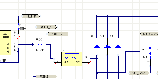
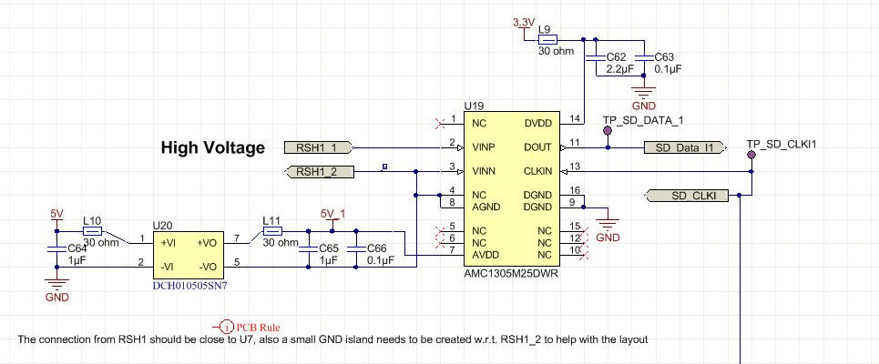
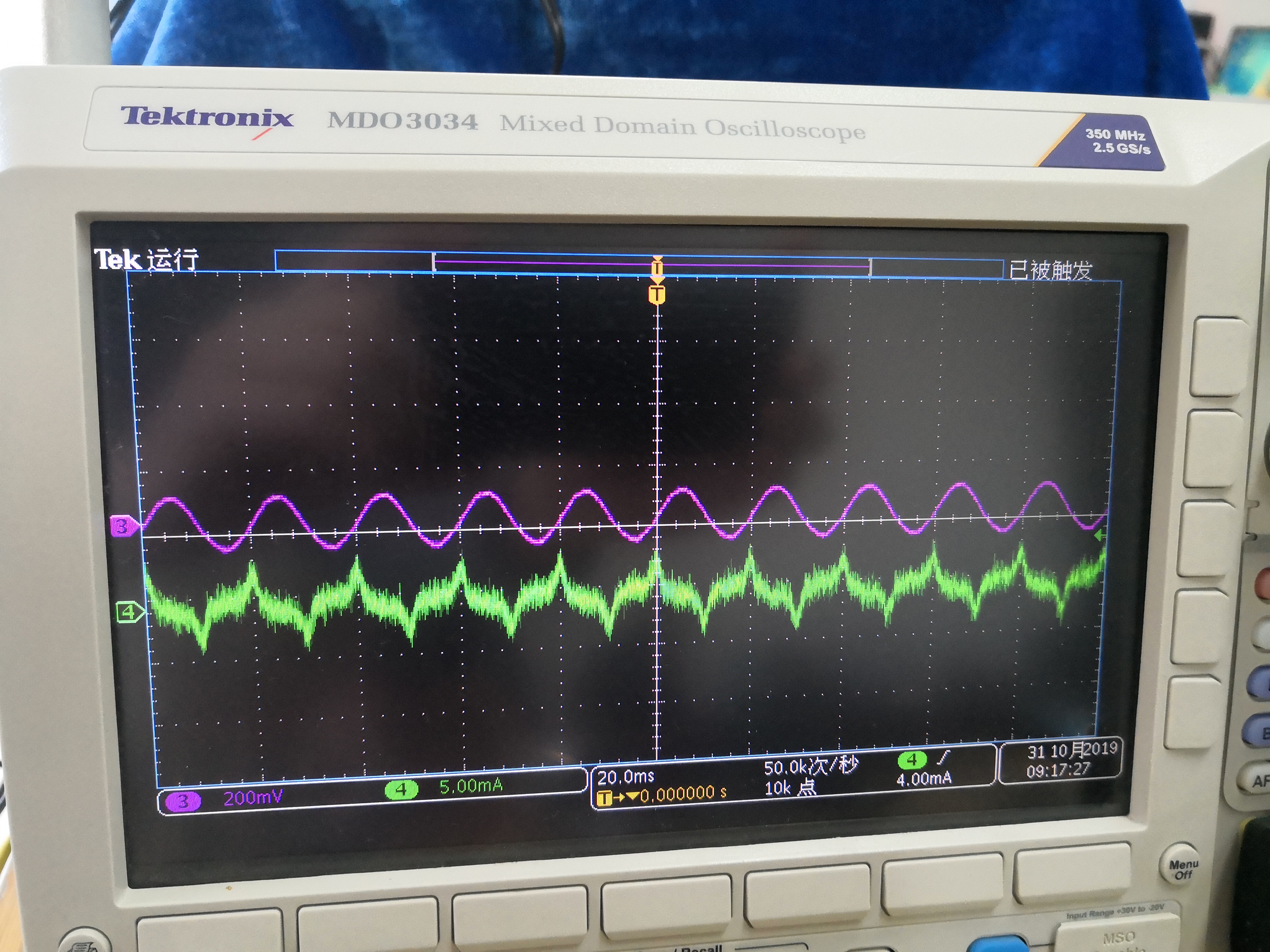
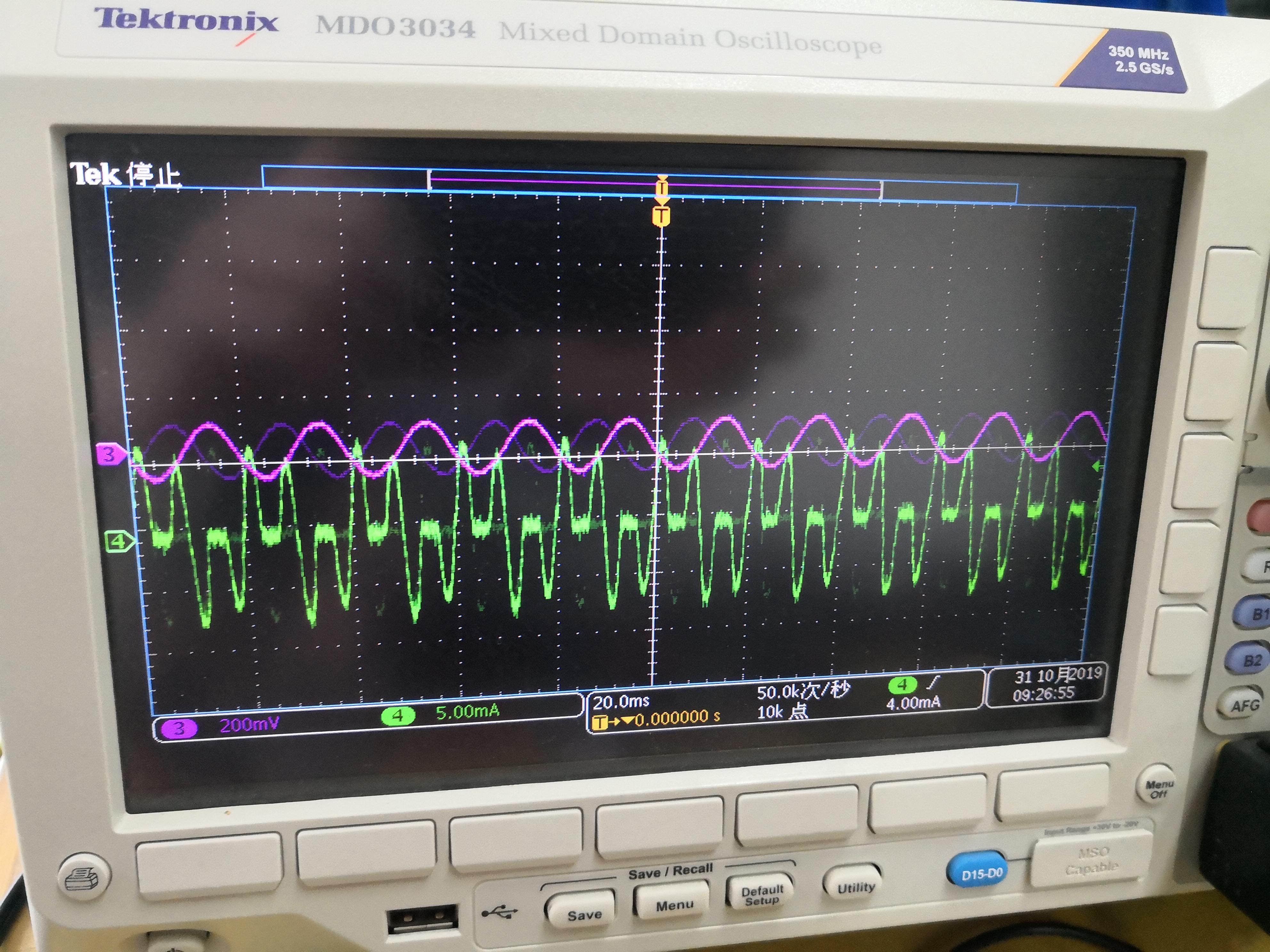
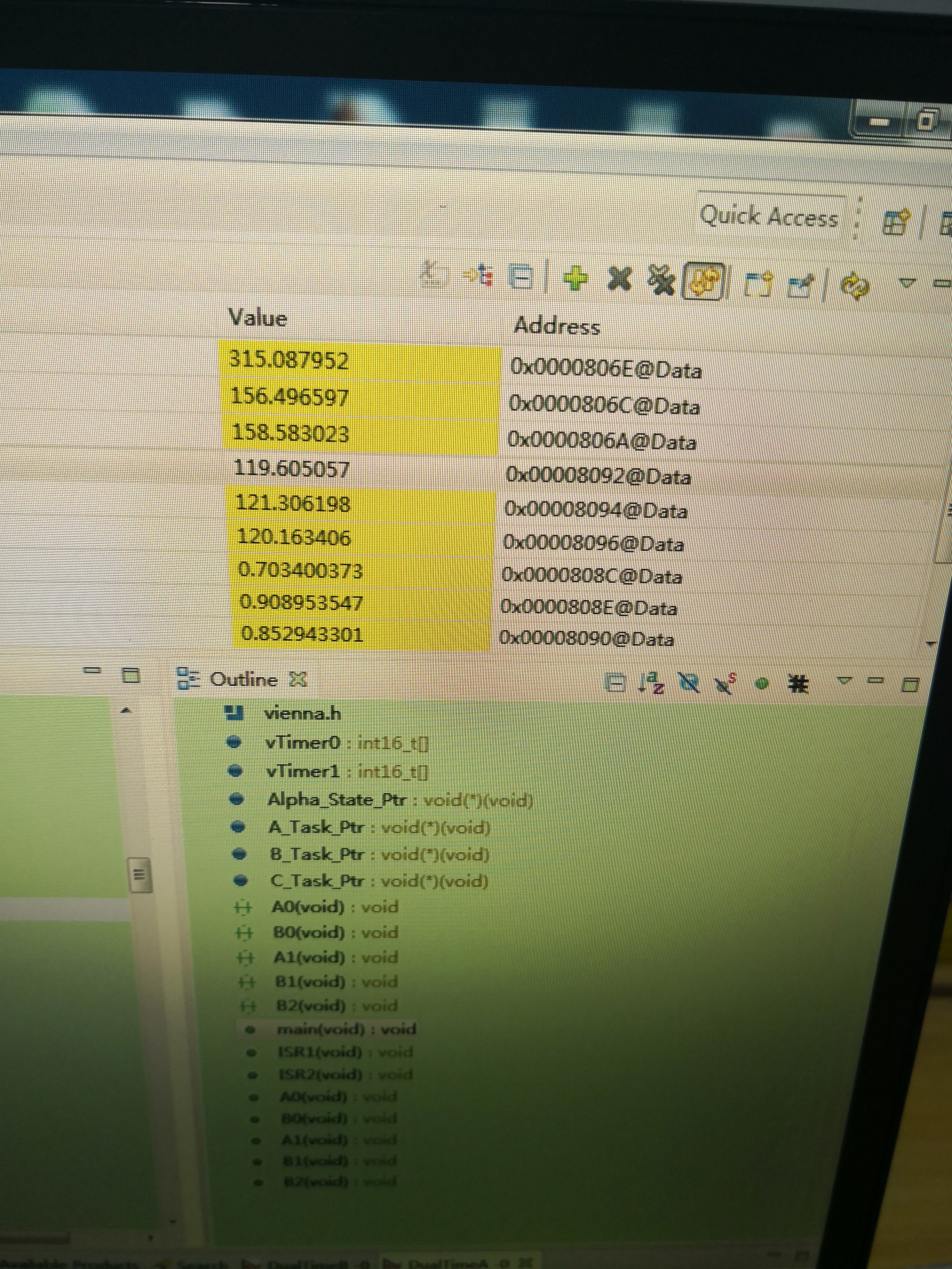
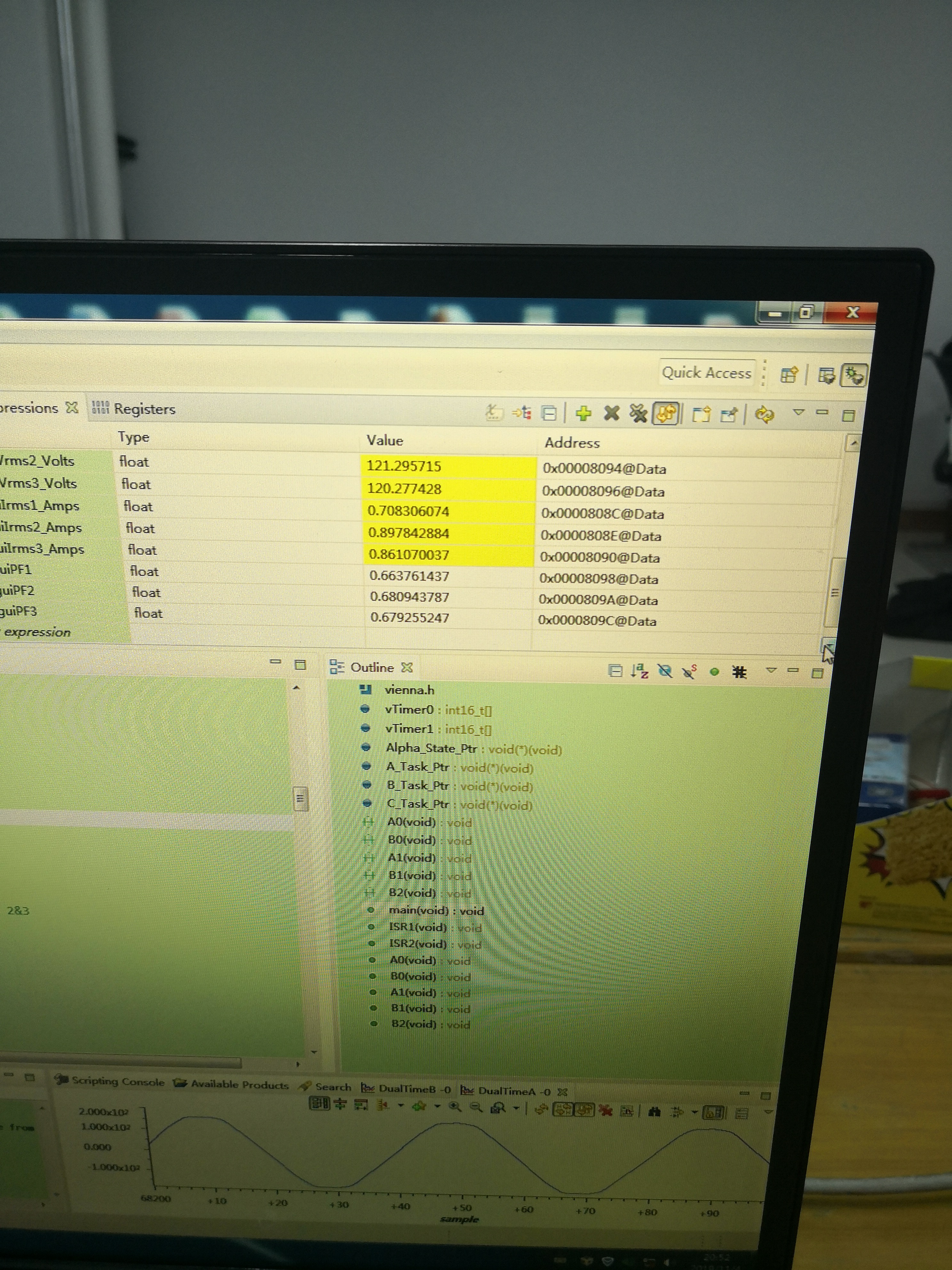
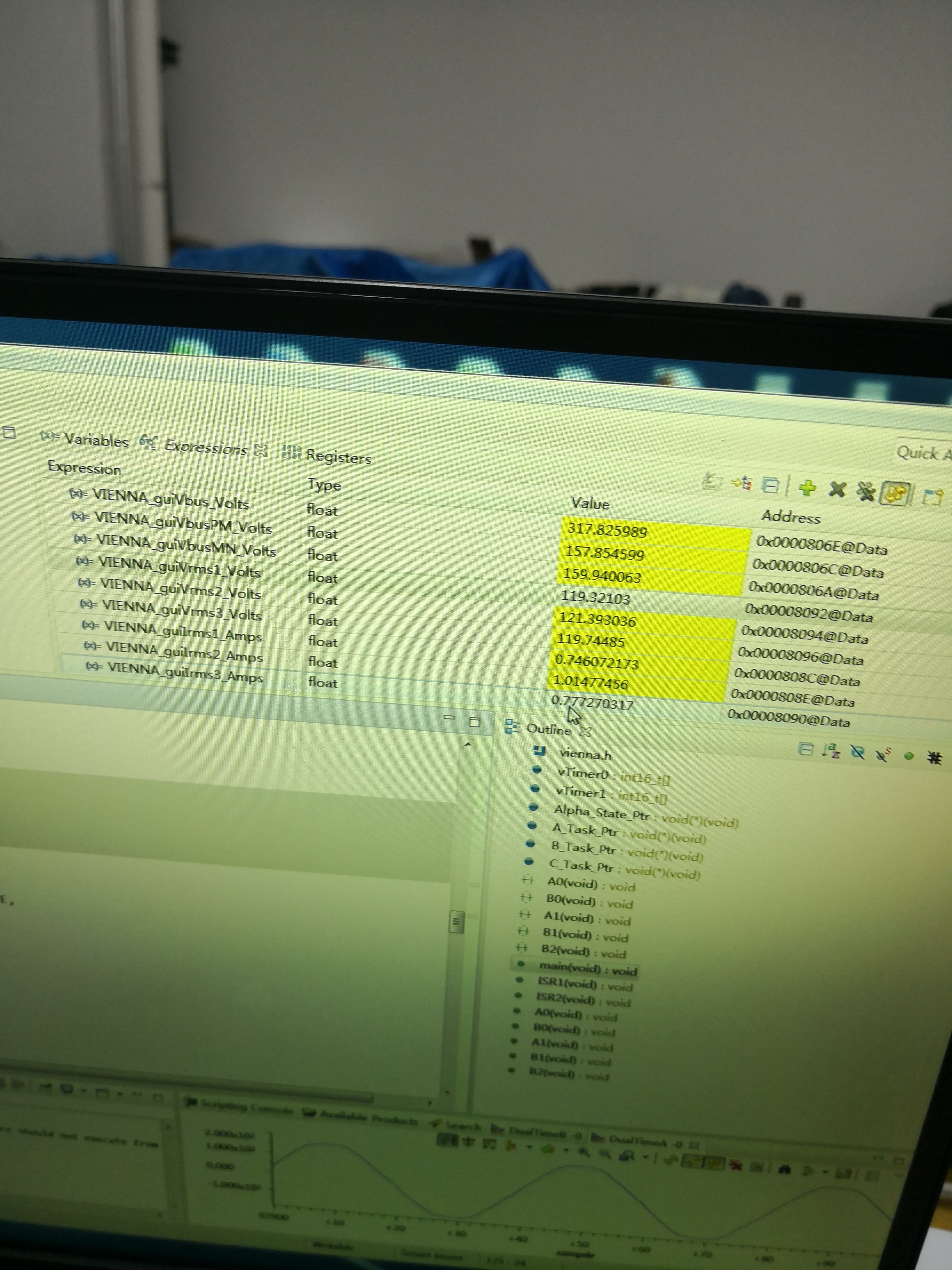
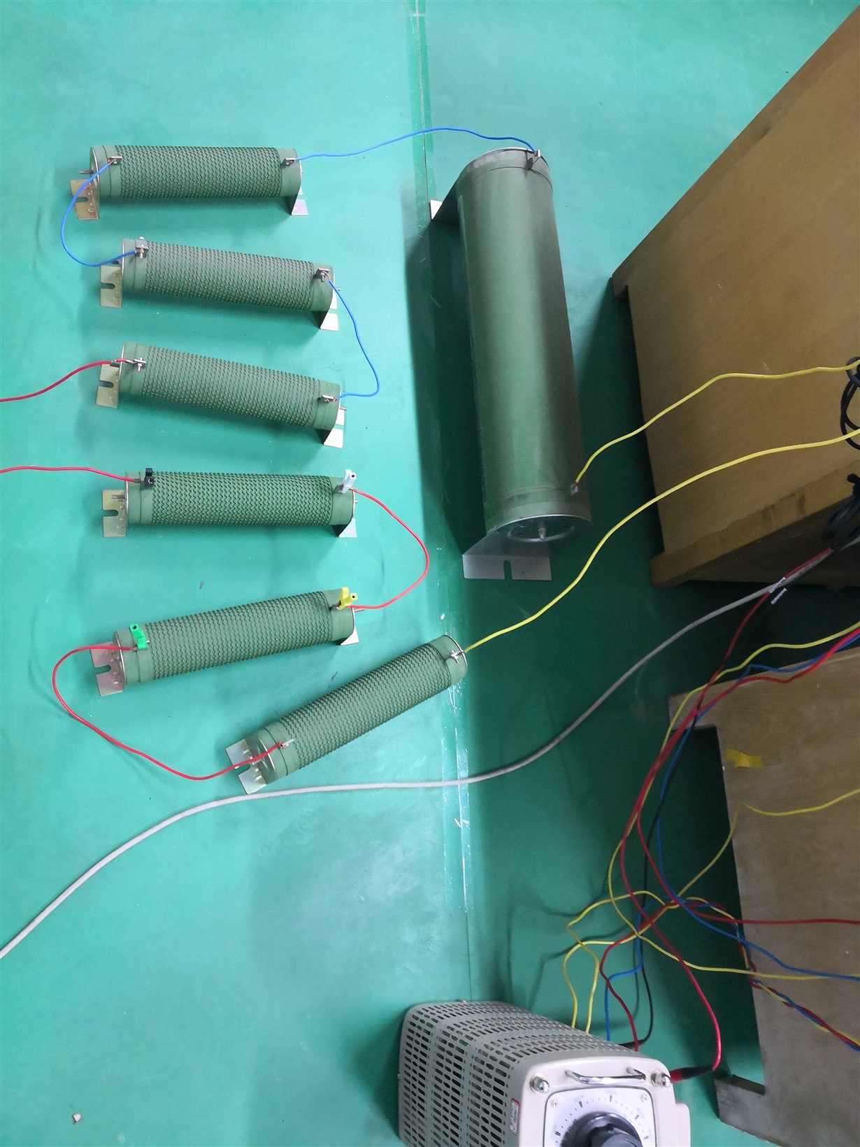
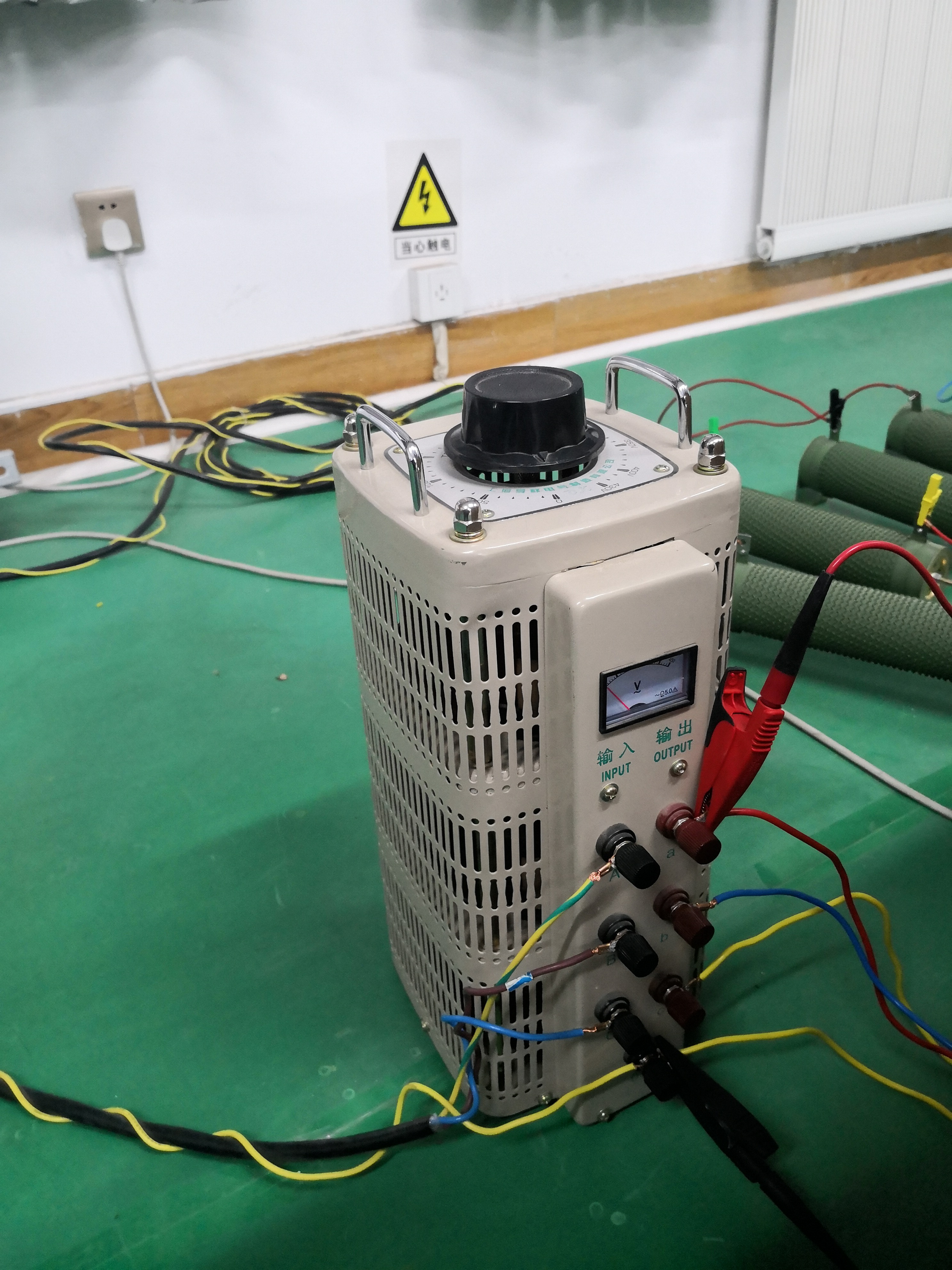
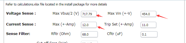
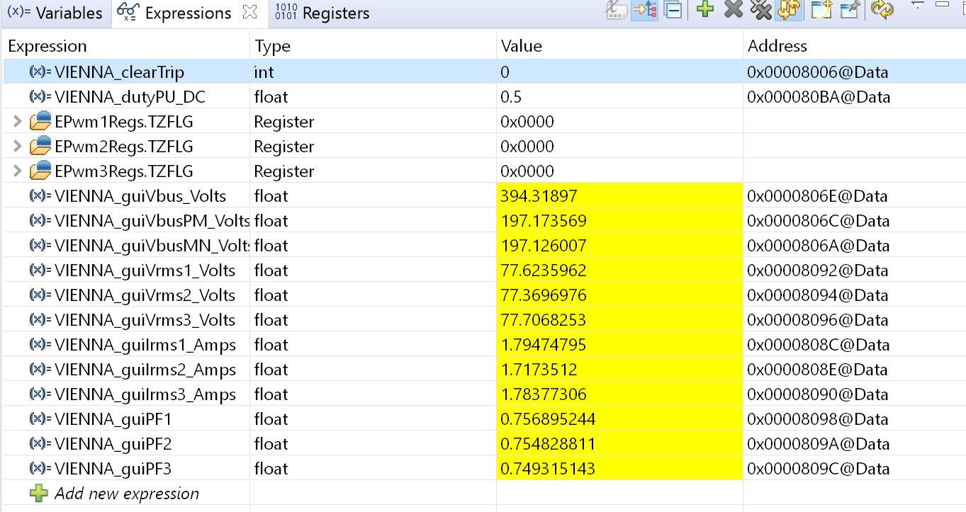
1.What should I do? Can this board continue to work?Capacitor C1 blew up and AC voltage sampling chip burned out.

I followed the steps in build 3. The AC voltage went up to 120V, and then I turned on the PWM. In a flash, the DC voltage went up to 600V, and the capacitor C1 exploded.Why did it explode? Is it because C1 has insufficient withstand voltage? How did AC voltage sampling chip burn out?

  • Hi,

    Sorry to hear that. Like I suggested in another thread, we have to make sure everything is fine in build 2 first before starting build 3. It is hard to make a judgement for the board, but ideally you should be able to replace the broken components and make it work. Also please make sure the current protection is on and try to verify it before moving it to build 3. You also have to check the FETS and driver. Thanks.

    Regards.

    Chen

  • I asked you in another thread, but you did not answer me the day before yesterday, only answered one of the questions, I thought you would not reply, so I can only try to boost pressure according to my plan. If you reply to me in time, maybe the board won't break.

    As shown in the figure below, capacitor C1 exploded and current sampling chip burned, but this sampling chip is not used at all(The first picture U19 is a current sampling chip, not an AC voltage sampling chip.). Can you give me an analysis of the reason?

  • The C1 blown up here is useless.Because the rear U1 is not welded on the circuit board,Why did C1 blow up here?

  • But C1 is still connected between VBUSM and VBUSN. I assume it is because of the unbalanced input causing the output voltage to be larger then the cap voltage limit.

    Please let me know if you have made any progress in repairing the board.

    Regards,

    Chen

  • Hi,

    Since I don't get the response from you, I will go ahead to close this thread. Please feel free to create another thread if you have any questions. Thanks.

    Regards,

    Chen

  • No,C1 is connected between VbusN and netural potential point.Why the input always unbalanced?What's wrong with the product?

    Today, I tried to power on again. Input 30V voltage, phase a shows voltage, no current, the main side of the voltage regulator has current and is normal, phase B, phase C shows normal, phase n has current, I don't know why

    Phase A  voltage(Violet) and Current(green)

    Phase B 

    Phase C

    Phase a of main side of voltage regulator  

    N phase current,Voltage not.

  • Hi,

    I doubt there is still something wrong in the baseboard causing this unbalanced current issue. Usually it takes time to debug.

    1. To also measure the PWM signal for all three phases to make sure they are correct.

    2. The good thing is your three phase input voltages are balanced based on the waveforms you provided. I remember earlier you see unbalanced input voltage showed in the watch window. So I assume this has been solved because of the voltage source.

    But the voltage you showed is in a level of 200mV. So is this the sensed input voltage?

    3. The peak current is around 5mA? With 30V input, it seems too low. So it is not the real input current? 

    You need to measure the real phase current. If there is no phase a current, it can be some component broken on the board or because of the abnormal behavior of PWM signal. I will suggest to do hardware examination for phase a after checking the PWM signals.  

    4. The neutral line current is caused by the unbalanced three phase current so it is not a surprise when there is no phase a current. 

    Regards,

    Chen 

  • Hi,
    1.After checking the board, it's confirmed that it's open circuit. Now it's recovered
    2.Because the last time the board broke, it took me a long time, so I need to be very careful this time.
    Today, I tried open-loop debugging. As shown in the figure below, my AC voltage is 120V, but my DC voltage is not 320v, only 314v. Is this within the error range? The three-phase current is 0.70/0.90/0.85a respectively, which is not up to 0.92a mentioned in the manual. Is the current amplitude and the difference between each phase current within a reasonable range?

    Voltage (purple) and current (green) are measured by voltage probe and current clamp respectively, with gears of 500 times and 100 times respectively.

  • Hi,

    I would say 314 is ok. 

    Phase a current is a little bit low. Manish has gave you two suggestions, please check them again.

    Once you fix it, you are good to go to the next step. And you can also test the over current protection in the code and enable the current/voltage protection in your source. 

    Regards,

    Chen

  • Hi,

    I have checked the board according Manish says, The test results are shown in the figure below

    In the first picture,Purple is A-phase AC voltage, green is A-phase AC current, blue is B-phase AC current.

    in the second picture, Purple is A-phase AC voltage, green is A-phase AC current, blue is N-phase AC current.

    Q;1.Does the magnitude of surge resistance have a great influence on the magnitude of current?This morning, I measured 18.1 / 19.6 / 18.2 ohms of surge resistance, which changed to 14.2 / 15.5 / 14.3 ohms at night. If there is an impact, how can I reduce it?

       2.Manish mentioned that surge resistance needs to be heated evenly. How long should I wait?

     I look forward to your reply!

  • Hi, 

    The Inrush NTC we used are very variable, so this can happen. We suggest to remove the inrush NTC and check if this is still unbalanced.

    Also you have to be careful if you remove NTC to apply sudden voltages. 

    Regards,

    Chen

  • Hi,

         I removed the surge resistor, and the current is still unbalanced, which is basically the same as before. Where else do you think there might be a problem? Is it all like this in the open loop? Do you have any reference data in the laboratory for me to refer to?

          I'm really in a hurry because it's about my graduation project. The efficiency of our e-mail communication is particularly low. Do you have any practical plans? Is there an engineer's phone? I can communicate directly, or I can communicate directly through case. What should I know clearly, or which parts of the devices I should check? Your products are not always tested before they leave the factory. Why did I start debugging in July and encounter so many problems, and still stay in the open-loop stage?

          I hope you can understand. I hope to see your reply as soon as possible. Thank you!

  • Hi,

    I can understand your concern, but this is something we didn't see before from other customers in terms of the Hardware. Based on our test, we usually don't see this issue in our test. And like we suggested, it is expected to be related to the NTC if it happens. But it is not in your case. Now you have to isolate the problem and try to figure it out since this is your project but we will try our best to give you suggestions through emails(although because of the time zone, I understand it is not very efficient).   

    My guess is that it is probably related to the internal impedance of your AC source. Could you also try connect to other AC load directly without this board if you have in your lab and test if the current are balanced?  Let me discuss with my colleagues and try to give your more updates. Thank for your patience.

    Regards,

    Chen

  • Hello,

    1.do you mean to replace a voltage regulator?Today, we use three-phase voltage regulator sub side a, B, C three-phase to connect a 50 ohm resistance respectively, and then connect them to n-phase together. After testing, the current is balanced (about 0.5A). Do you know whether it is useful to test the voltage regulator in this way?

    2. Is it possibly caused by the asymmetry of diode parameters?

    3.Now it's just uncontrolled rectification. Can you list all the possible causes of imbalance? I'll check them one by one

    Thank you!

  • Hi,

    Noted we didn't measure the neutral current since this is designed as a three wire solution, so we are not sure what causes the asymmetry neutral current. Maybe there are still some broken components in the board. I will suggest to check the board again such as the diode and bus cap. Make sure the voltage/current protection is working correctly. This level of imbalance might be acceptable. Then you probably can go ahead to start to close the current loop with 40V input as mentioned in the user guide (do not directly close the loop with 120V input). If it is working ok, then slowly increase the input voltage and monitor all the parameters carefully in the expression window. Thanks.

    Regards,

    Chen

  • As shown below, it is the three-phase current under the open-loop, current loop and voltage loop. They are asymmetric. 2 (cyan) is C phase, 3 (purple) is a phase, 1 (blue) is B phase. Can you help me analyze what caused it? I haven't seen the three-phase current before, but now I find that it's not symmetrical. There's a problem with the phase

    1.open loop

    2.cuuent loop

    3.voltage loop

  • Hi,

    Ok, so basically your three phase current are not 120 degrees apart. Have you plotted the three phase input voltage waveforms? Are they 120 degrees apart from each other?

    Regards,

    Chen

  • Hi,

    Do you get any progress or updates?

    Regards,

    Chen

  • The current clamp is reversed.

  • There's no progress recently. I'm looking at the code. There's a problem today

    Why does the current value displayed on the upper computer multiply by 12A?
    The IL1 / 2 / 3 here can be understood by multiplying by 12a if sdfm sampling is used
    But the hall sensor used here
    Is the formula in the last figure current or voltage?
    I hope I can get back to you as soon as possible. Thank you
  • There's no progress recently. I'm looking at the code. There's a problem today

    Why does the current value displayed on the upper computer multiply by 12A?

    The IL1 / 2 / 3 here can be understood by multiplying by 12a if sdfm sampling is used

    But the hall sensor used here

    Is the formula in the last figure current or voltage?
    I hope I can get back to you as soon as possible. Thank you
  • Hi,

    Could you please explain a little bit further about "The current clamp is reversed."? Is there anything wrong in the hardware you noticed?

    Have you checked the three phase input voltage waveforms?

    Regards,

    Chen

  • Hi,

    To answer your questions above:

    1. 12A is the ADC current reference

    2. ADC and SDFM have different reference value

    3. the formula you mentioned is for current sensing. But it is a voltage value representing the current.  

    Next time please create a new thread for these software related questions. 

    Regards,

    Chen

  • Ok,I mean, the direction of the AC current probe  is reversed.There's no problem now.

  • 1.I mean, why do I multiply by 12a, can I not?

    supplement:

    1.We bought the same power board again. Now we still have the problem of current imbalance. The parameters are similar to those of a board.

    2.Have you ever tested at 50Hz? What's the test result? The power supply in China is 50Hz. Have Chinese users ever fed back relevant test results to you before? I'm doing experiments here. I really need reference. I have carried out the simulation under the uncontrolled rectifier, the voltage is set at 76.89/77.67/77.64v, and the current output is unbalanced. Please help me find a solution. My problem is also promoting you to improve the product.

  • Hi,

    1. Ok, let's make sure we are talking about the same thing. The current imbalance is acceptable if the current value under light load/low input voltage is something close to 0.74/0.92/0.75 like you told me last time. However, the less than 120 degree phase shift of three phases current is not acceptable which I call it asymmetric current in this case. So which one are referred to? imbalance or asymmetric current?

    2. I will rerun the solution on my side to see if I can reproduce the issue you encounterred. Could you please wait for one week and I will get it back to you because we are close to Thanksgiving and we need to setup our test here in our lab. To be honest, we have not received any other similar issues as you saw in your test. But I am not excluding the possibility of a potential new bug. Thanks for your patience. 

    Regards,

    Chen   

  • 1.I mean, why do I multiply by 12a, can I not?

    This is just to transfer a PU value to a real value(GUI value). The GUI value is not for control. It is for indication.

    Regards,

    Chen 

  • 1.Ok.Let me answer the first question.As shown in the figure on the left, I placed the current probe in the same way at the beginning; later, I placed the current probe in accordance with the figure on the right, and the phenomenon of current asymmetry disappeared, so there was no problem of current asymmetry. I got the current direction wrong

    2.I'll give you a brief account of the laboratory so that you can restore it. As shown in the figure, it is the resistance on the load side: Six 50 ohm (1kW) resistances, one 200 ohm (10kW) resistances,

    The input side is connected with a 6KVA voltage regulator,Voltage adjustable input, frequency 50Hz.

    This is a Simulink model under uncontrolled rectifier, you can see

    Bukongzhengliu.rar

  • 2.
    How is Max VIN here determined? How to determine the maximum value of current sampling? I saw the calculation in the calculation.xlsx, but the max VIN calculated in it is 416.917v, which is different from here. What resistance is the Rdiff in the table? How to make sure? Is there any formula to support it?
  • Hello, it's been more than half a month. How is your test?

  • Hi,

    I have retested code based on F2837x and I don't see anything wrong with build 1 and build 2 with 50kHz. Please see the expression window as below:

    Build 1:

    Build 2:

    You can see that with open loop, there is minor imbalance for three phase current. But with current closed loop, the imbalance is negligible. Can you compare your expression window with mine to see if there are any difference there? 

    Also, the neutral line current exists when input current is not sinusoidal. 


    Regards,

    Chen

  • hello,

    1.Is it tested at 50Hz AC?My previous problem is that at 50Hz AC, it has nothing to do with 50K switching frequency

  • Sorry, I mean 50Hz. 

    Regard,

    Chen

  • Hi,

    Could you please let me know if you are able to run all the builds based on the user guide now?

    Regards,

    Chen

  • Since I have not got a reply from you and this thread is too long to chase back, I will go ahead and close it. Feel free to create a new one if you have any other questions. Thanks.

    Regards,

    Chen