This thread has been locked.

If you have a related question, please click the "Ask a related question" button in the top right corner. The newly created question will be automatically linked to this question.

How to measure successfully the frequency response of the buck converter based on SFRA

Other Parts Discussed in Thread: SFRA

Dear Support,

I am using the SFRA tool to obtain the plant and open loop frequency response of the buck converter system controled an F28035.According to the SFRA Module User ‘s Guide,I have added the necessary codes and function.Now ,I find the results measured recently are different from the ideal outcoms. But the whole system is not stable and has strong oscillation,so,I cannot use the Compensation Designer to design compensator.     Therefore, could you please provide me with an assist about how to measure the right bode plot of the buck converter ,i will be appreciate you,thank you.thank you.

This picture describe the ideal results.

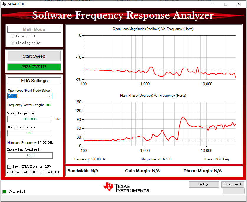
the next picture represent the unsatisfactory results measured by my own

  • user6184829,

    I noticed that you have "Floating Point" selected in Math Mode of the SFRA GUI.  My understanding is that F2803x does not include a native FPU so you are probably using fixed point IQ math in the program?  If so, you will want to use the "Fixed Point" selection instead.

    -Tommy

  • sorry,in fact,that 2806x is my microcontroller concluding a native FPU,where is right haing "Floating Point" selected in Math Mode of the SFRA GUI.i think that another factors resulting in the worse results.Thank you.   

  • Can you confirm that your control software is using FPU floating point representations instead of IQ-math?  Some examples use IQ-Math even on devices that include FPU hardware.  The GUI selection should match the software implementation, not the hardware availability.

    Are you using a TI-created software example and hardware or is it custom?

  • Firstly,I want to appreciate you for that you spent time in replying my question.The picture above that is a TI-created software example embody the current project which 2806x is my microcontroller concluding a native FPU.However,Hardware platform is developped by myself according to the Ti's examples.

  • user6184829,

    It does appear to me that the example is using fixed-point IQ math.

    	cntl3p3z_vars1.Fdbk= _IQsat((((float32)Vout1R*ADC_PU_SCALING)-offset_Vout),1.0,0.0);
    
    	//Update PWM value
    	EPwm1Regs.CMPA.half.CMPA= _IQ24mpy((long)(BUCK_PWM_PERIOD),cntl3p3z_vars1.Out);
    
    	SFRA_F_COLLECT(&cntl3p3z_vars1.Out,&cntl3p3z_vars1.Fdbk);

    You can also inspect the contents of the SFRA sweep data arrays to confirm:

    float32 Plant_MagVect[SFRA_FREQ_LENGTH];
    float32 Plant_PhaseVect[SFRA_FREQ_LENGTH];
    float32 OL_MagVect[SFRA_FREQ_LENGTH];
    float32 OL_PhaseVect[SFRA_FREQ_LENGTH];
    float32 FreqVect[SFRA_FREQ_LENGTH];

    I think it makes sense to try the fixed-point option in the GUI.