Tool/software: Code Composer Studio
Hi community,
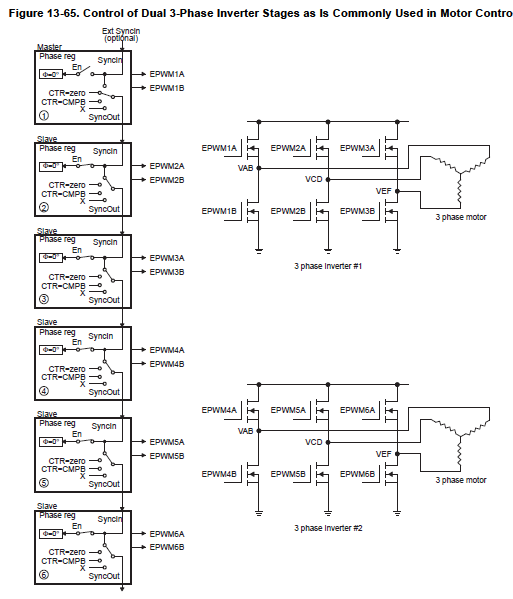
I wan PWM1, PWM2, PWM3, and PWM11 be in phase together (synchronous operation with zero phase delay). What should I set for:
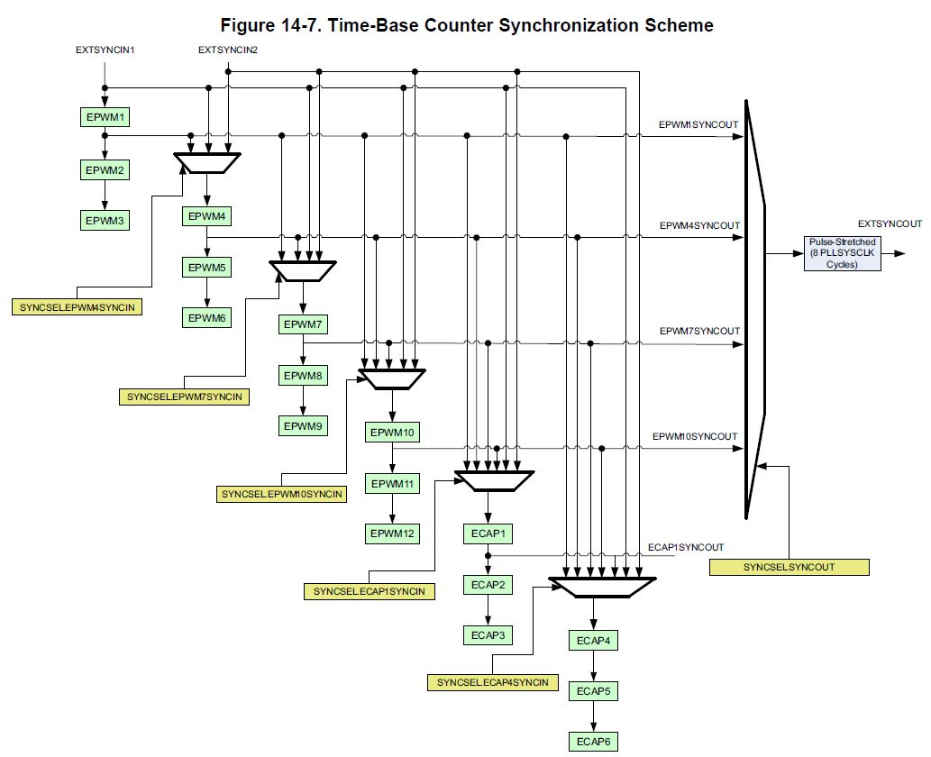
EPwm1Regs.TBCTL.bit.SYNCOSEL
and
EPwm2Regs.TBPHS.bit.TBPHS,
EPwm3Regs.TBPHS.bit.TBPHS,
EPwm10Regs.TBCTL.bit.SYNCOSEL
EPwm11Regs.TBPHS.bit.TBPHS
Considering 2 cycle logic delay between master and slaves, should I set TBPHS as follows?
EPwm2Regs.TBPHS.bit.TBPHS=2;
EPwm3Regs.TBPHS.bit.TBPHS=4;
EPwm11Regs.TBPHS.bit.TBPHS=4;
Regards.