This thread has been locked.

If you have a related question, please click the "Ask a related question" button in the top right corner. The newly created question will be automatically linked to this question.

TMS320F280049: CMPSS + EPWM Peak Current Mode Control (PCMC) Configuration for Phase-Shift Full-Bridge Converter

Part Number: TMS320F280049
Other Parts Discussed in Thread: CONTROLSUITE

Hi all,

1) Is there any source-code/example to use CMPSS + ePWM to drive a phase-shift full-bridge converter using peak current mode control?

2) I am new to CMPSS, especially in TMS320F28004x, can anyone provide CMPSS and ePWM module configuration for my application?

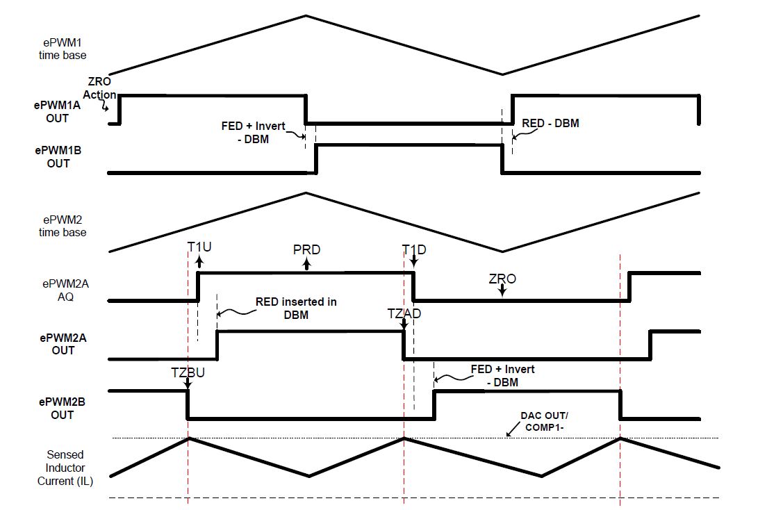
I found SPRABR1 which is a useful application note. However, it only gives the working logic behind PCMC in TI DSP without the code example.

Thank you for your help.

Best regards,

Adhistira

  • Hi Adhistira,

    1)  For f28004x based PCMC PSFB, we will probably have an example at the end of 1Q2020 in our digital power sdk. 

    2)  For f2803x based solution, the example is in controlSUITE/HVPSFB. You can download controlSUITE for the details. For f28004x based solution, please refer to the pic below for EPWM configuration. 

    For CMPSS configuration, you can use CMPSS High channel for peak current comparison since it supports slope compensation in the hardware. Low channel can be used for over current protection. So you only need single pin to implement both functions.

    Regards,

    Chen

  • Hi Chen,

    Thank you for your kind answer. 

    I have more question about the setting:

    1) What is the function of ePWM2A AQ? is it to determine which TZ (TZxU / TZxD) should act upon receiving the signal from CMPSS? How to configure?

    2) Can I update the slope value of the ramp generator while the converter works? Is it by continuously changing the RAMPDECVALA value?.

    3) Is it right to set COMDACCTL[DACSOURCE] = 1 and the peak current reference fed to RAMPMAXREFS?.

    Kind regards,

    Adhistira

  • 1) What is the function of ePWM2A AQ? is it to determine which TZ (TZxU / TZxD) should act upon receiving the signal from CMPSS? How to configure?

    ePWM2A AQ is the source for real EPWM2A output and EPWM2B output(mainly adding the deadband to trigger rising edge). TZBU and TZAD are used to trigger falling edge.  

    Specific configuration:

    The EPWM1A and EPWM1B outputs are complimentary and 50% duty cycle are maintained based on the action qualifier and deadband settings. The EPWM2A/B_AQ(action qualifier output) is set to 1 when T1U(T1 with counter counting up) event occurs and when counter reaches PRD. The EPWM2A_AQ is set to 0 when T1D(T1 with counter counting down) event occurs and when counter reaches ZERO. The T1D and T1U event are triggered by DCAEVT2.

    With type-4 PWM, the deadband can be directly added to T1U and T1D event without adding extra code configurations. The rising edge delay is inserted For EPWM2A. And falling edge delay is inserted for EPWM2B together with inversion accordingly.

    To achieve the quickest response, the trip zone modules are utilized to setup the falling edge for EPWM2A (with TZAD event) and EPWM2B (with TZBU event) output. The cycle by cycle trip is implemented and is required to be cleared on ZERO and PRD event.

    2) Can I update the slope value of the ramp generator while the converter works? Is it by continuously changing the RAMPDECVALA value?

    Yes, you can. No, you need to change the RAMPDECVALS. Please take a look at page 1692 of TMS320F28004x Microcontrollers Technical Reference Manual.

    3) Is it right to set COMDACCTL[DACSOURCE] = 1 and the peak current reference fed to RAMPMAXREFS?

    Yes, that is correct.

    Regards,

    Chen