This thread has been locked.

If you have a related question, please click the "Ask a related question" button in the top right corner. The newly created question will be automatically linked to this question.

2MTR-DYNO: Units of measure for controlling through Simulink

Part Number: 2MTR-DYNO
Other Parts Discussed in Thread: LAUNCHXL-F28379D
Good evening,
I am using the 2MTR-DYNO kit with the TI F28379D LaunchPad with 2 BOOSTXL-DRV8305 booster packs.
The code that i load on the board is obtained by playing the Simulink model obtained through commands c28379Dpmsmfocdual_cpu1_ert and c28379Dpmsmfocdual_cpu2_ert.
(It performes a Permanent Magnet Synchronous Motor Field-Oriented Control). 
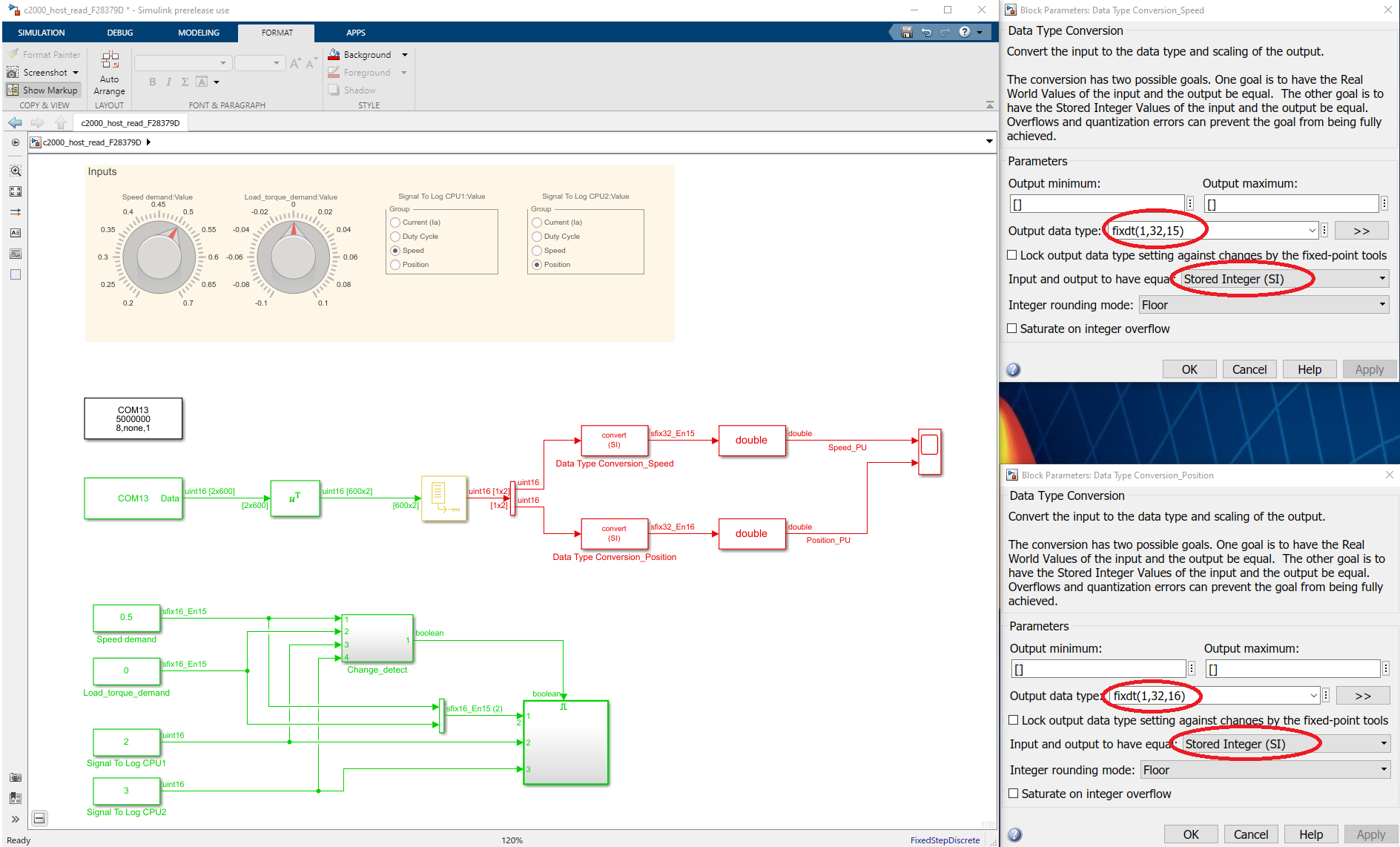
I am also using the Matlab instruction c2000_host_read_F28379D, in order to get data from the boards.
Everything seems to work weel, but I really don't find out which UNITS OF MEASURE I see in the 4 plots of c2000_host_read_F28379D.
Now, questions about the two circular indicators:
1) the Speed Demand from 0.2 to 0.7 what does it mean? Is a percentage of the maximum speed of the motor?
Because I don't find any connection between that value and the plotted signal of speed.
2) Regarding the load torque demand: is it Newton per meter ?
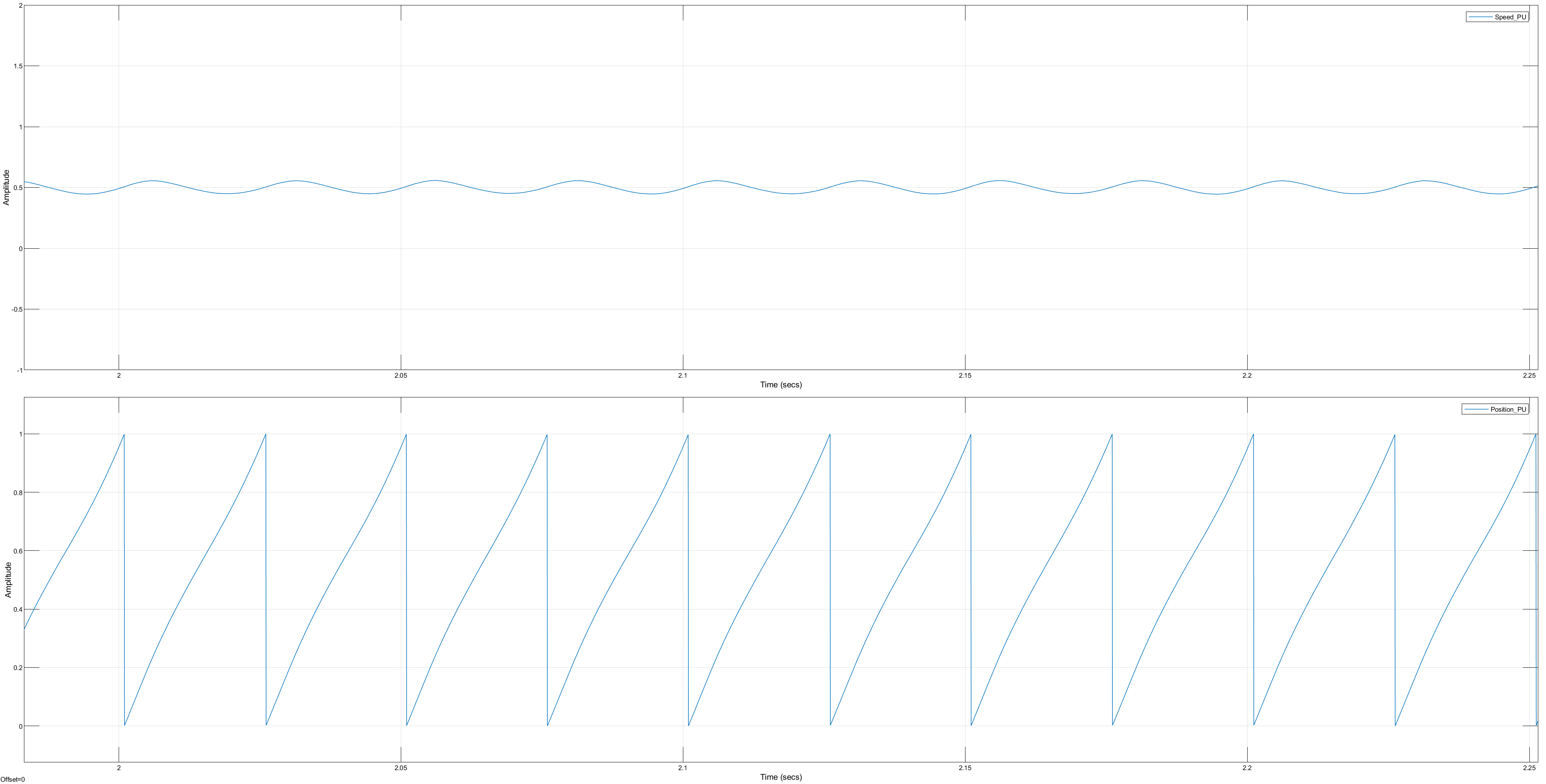
After that.. about the plots: for current I suppose they are milliAmperes, since the sinusoidal curves have average value of 2300, but I'm still not sure. Is it like that?
3) What about speed, duty cicle and position? I am very interested in understanding above all the unit measure for the speed, since it seems to be grades/second.
Could it be?
Thank you,
I hope you can help me
  • Hi Veronica,

    Welcome to the world of fixed point in embedded systems. You may learn fixed point representation of numbers & IQMath by TI's resources separately. To keep it simple: We are using a ‘per-unit’ representation of signals applied to embedded systems. This helps in generating optimized code, especially when working with fixed-point data types. Also, the signals represented in PU system range from -1 to +1, as against a large number for an equivalent SI unit. You can use the following formula to convert signals from PU to SI units and vice-versa.

    quantity expressed in PU = (quantity expressed in SI units)/(base value)

    OR, as per your requirement:

    quantity expressed in SI units = quantity expressed in PU × base value

    The base values used for speed, current and position signals in the example mentioned by you are given below:

    • Base speed, Speed_base = 1200 rpm
    • Base current, I_base = 19.3 A
    • Base position, Theta_e = 2*pi (radians)

    Now coming to your questions: 

     ===========================================================================

    1) The Speed Demand from 0.2 to 0.7 means per-unit speed w.r.to. base speed.

    The variable ‘Speed_per_unit_scaler’ in MATLAB workspace represents the base value of speed.

    You may use the above described formula, to convert these signals from PU system to SI units. If you wish, you may change the base speed to maximum speed of the motor by updating the workspace variables.

    These variables are initialized when the Simulink model is loaded. You may access the initialization script by going to model properties-->Callbacks.

    Alternately, you may also type ‘edit c28377pmsmfoc_data’ at MATLAB command window to open this models’ initialization script.

     =========================================================================

    2) Regarding the load torque demand: 

    The load torque in this example is PU value for q-axis current of the load motor. You may use the base value for current to convert this into amperes. Then, you may use the following conversion to get torque in Newton-meter (NOT Newton-per-meter):

    Tem = (3/2)*(polePairs)*(FluxPM_weber)*Iq_amps

     about the plots: Current

    As for the current signal: What is being displayed is the output count of ADC. Inside the algorithm on the target, it is converted into per-unit by following approach:

    Ia_PerUnit = (Ia_ADC_Count – ADC_Offset)*AdcVoltsPerCounts*AmperePerVolt*(1/I_base)

    Where,

    • Ia_ADC_Count = Signals you see on the host model
    • ADC_Offset = 2300 (approx.) // This is ADC Count at zero current (~1.65V at ADC for this example)
    • AdcVoltsPerCounts = (1.65/2048)
    • AmperePerVolt = (19.3/1.65)
    • Base current, I_base = 19.3 A

    Similar calculations are used for Ib. You may convert the currents from per-unit to amperes using the base current mentioned above.

    ============================================================

    3) What about speed, duty cycle and position?

    Unit of measure for speed is PU. As explained, you may multiply by base speed and convert to RPM. This can further be converted to any other units (e.g. rad/s) 

    Duty cycles: These are counts for ePWM block. The variable ‘PWM_Counter_Period’ in MATLAB workspace describes equivalent count for 100% duty cycle. You may convert the duty cycles accordingly.

    Position is per-unit representation of 2*pi radians. You may multiply by 2*pi and convert to radians. Or convert to any other units (e.g. degrees) of your choice.

     =================================================

    Because I don't find any connection between that value and the plotted signal of speed.”

    Thanks for pointing this out. We are coming up with much better documentation for Motor Control examples in R2020a. 

    Hope this was helpful.

    --

    Darshan Pandit | MathWorks

  • Hi Darshan Pandit,

    Thank you for your exhaustive answer but I still have some doubts.

    ------------------------------------------------------------------------

    Darshan Pandit said:

    Unit of measure for speed is PU. As explained, you may multiply by base speed and convert to RPM. This can further be converted to any other units (e.g. rad/s) 

    I understood the part of PU measures, but in the speed plot I have the following results:

    With 0.2 PU speed demand (and 0 load torque demand) , the plot speed of Motor 1 (CPU1) oscillates from 4000 to 9000... which unit of measure is it in that case? 

    In the same way, with 0.45 PU speed demand, the plot speed of CPU 1 fluctuates from 1.3x10^4 to 1,63 x 10^4.

    ------------------------------------------------------------------------

    Darshan Pandit said:

    The load torque in this example is PU value for q-axis current of the load motor. You may use the base value for current to convert this into amperes. Then, you may use the following conversion to get torque in Newton-meter (NOT Newton-per-meter):

    Tem = (3/2)*(polePairs)*(FluxPM_weber)*Iq_amps

    Which is the value of FluxPM_weber and Iq_amps??

    Thank you a lot,

    Veronica

  • Hi Veronica,

    One thing I missed in the post above is: The target model converts the signal data-types to uint16 before sending them over serial. This happens at following subsystem inside the target model: ‘c28379Dpmsmfocdual_cpu1_ert/FOC Alogrithm Motor/Data Logging’. Let’s call this signal data-type conversion as signal conditioning for briefness of the discussion here. This is explained below, prior to the solution you are looking forward to.

    =====================================================

    Signal Conditioning:

    The signal conditioning is not needed for duty cycles and ADC counts for currents, as these signals are already of ‘uint16’ datatype. However, the data-types of speed and position signals inside the target are fixdt(1,32,15) and fixdt(1,32,16) respectively. Hence, these signals require signal conditioning.

    The signal conditioning is implemented via representing last 16 bits of a fixed point as stored integer, and then, sending this as a 'uint16' data-type. The fixed point representation of the value 0.2 in given datatype, when seen as stored integer (uint16), corresponds to 6554 - which is around the average value of 4000 to 9000 you are observing in the scope. Similarly, the fixed point representation of 0.45, when seen as stored integer (uint16), corresponds to 14746. This again, is around the average of 1.3x10^4 to 1,63 x 10^4 as observed by you . To explore these, type the following at your MATLAB command prompt:

    a = fi(0.2,1,32,15);

    a.Value

    a.storedInteger

    The first command above stores the value 0.2 as a fixed point representation with Signedness = 1, WordLength= 32 bits, FractionLength = 15 bits. The second and third displays their value and stored integer representation respectively.

    =====================================================

    To get to the solution required:

    You’d have to modify the data-types of received signals in the host model. These would be different for speed and position respectively. The attached image would guide you better on this.

    Having done signal conditioning, you’d see the signals as expected by you: Per-Unit Speed (signal1) & Position (signal2).

    Once you can see these signals clearly for your hardware, you may start working towards solving problems such as tuning of PI controllers, Sliding Mode Oberserver, etc in the model.

    =====================================================

    Which is the value of FluxPM_weber and Iq_amps??

    Iq_amps is the q-axis current represented in amperes. As explained in previous post, the per-unit value of Iq is same as the torque demand (entered by you) in the host model. We need to convert it's value from per-unit to amperes, in order to compute the torque in N-m using the relationship provided.

    FluxPM_weber: is the value of permanent magnet flux represented in webers. This would be different for each motor. For the pmsm available with you, this can be computed by either back-emf constant (Ke) or torque constant (kt) using the following relationships:

    FluxPM = (Ke)/(sqrt(3)*2*pi*1000*polePairs/60); %PM flux computed from Ke

    OR

    FluxPM = (Kt)/((3/2)*polePairs; %PM flux computed from Kt

    Where,

    • Ke = back-emf constant with units as 'Vline_peak/krpm' (Vline = Vab)
    • Kt = toque constant with units as 'N-m/Amp'
    • polePairs = Number of rotor pole pairs of the pmsm

    Have a good day!

    --

    Darshan Pandit | MathWorks

  • Thank you very much. 
    Now everything is clear! :)

    I have only another question, about the "Base current, I_base = 19.3 A"
    Looking at the data that I have in my Workspace, the only current value I have is:

    motor.base_current=8.6 

    So, I suppose that I have to use that number instead of 19.3, is it right?


    Thank you for your support,

    Veronica

  • Hi Veronica,

    You are welcome.

    Thanks for highlighting this doubt. This requires a correction from our end.

    The variables from structure 'motor' (e.g. motor.base_current), seen in the workspace by you for this model, are only used for the tuning of Sliding Mode Observer. These are NOT used by the model anywhere. The reason for confusion: These variables are referring to an earlier example with DRV8312-69M-KIT. And these remain unchanged for the new targets (e.g. f28379d) since the SMO and PI parameters were tuned for those values. The values displayed (motor.base_voltage and motor.base_current) in workspace are different for F28379D+BoostXLDRV8305. This is also the reason why you can observe a room of improvement for tuning of PI controllers in the results. We'll fix this in future.

    While working with fixed point data-types, most of these values are decided by peripherals such as ADC, PWM Dutycycle, etc. For the model being used by you, please use the following values.

    • Base speed, Speed_base = 1200 rpm
    • Base current, I_base = 19.3 A
    • Base voltage, V_base = Vdc/sqrt(3) Volts
    • Base position, Theta_e = 2*pi (radians)

    Explanation for base value of voltage: This is the maximum phase voltage that inverter can supply to motor by using space vector modulation. Explanation for base value of current: The range for ADC measurements for LaunchXL-f28379D + BoostXL-DRV8305 is -19.3A to +19.3A. See this post for more details.

    Have a good day!

    --

    Darshan Pandit | MathWorks

    For more resources see: MATLAB Central 

  • Ok, thank you.

    I still have a couple of minor doubts.

    When you talk about PWM duty cycle.. to which signal is it applied? To the PU current?

    And then.. When you say "SI units" do you refer to Stored Integer or the Internation System of Units?

    I hope you can help me also with this issue.

    Thank you,

    Veronica

  • Welcome.

    The base voltage is decided by maximum phase voltage the inverter can generate using given PWM dutycycles:

    • For Sinusoidal Modulation, this is Vdc/2
    • For Space Vector Modulation, this would be Vdc/sqrt(3)

    SI Units =  Internation System of Units

    --

    Darshan Pandit | MathWorks

    For more resources see: MATLAB Central