This thread has been locked.

If you have a related question, please click the "Ask a related question" button in the top right corner. The newly created question will be automatically linked to this question.

LAUNCHXL-F280049C: Speed controller PI calculation discrepancies

Part Number: LAUNCHXL-F280049C
Other Parts Discussed in Thread: MOTORWARE

Hi,

I have few questions in the PI tuning of the Speed Controller. I am comparing these parameters between InstaSPIN-FOC User's Guide and the Code for the Lab 06 and 07.

  1. pUserParams->BWc_rps - Bandwidth of the current controller (rad/s)
    • Which is already converted in the rad/s from the user entered values (which is in Hz) in user.c file.
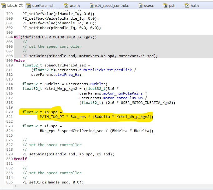
    • However, in the setupControllers(void) function, during the Kp_spd (P gain  for speed controller), it is again multiplied by MATH_TWO_PI. Which gives fairly high P gain value than expected.
    • The question is, Which equation is correct the one used in the code or the one in the User's Guide?
  2. pUserParams->BWdelta
    • Is it the damping factor (delta) mentioned in the chapter 11 of user's guide? If not what's the relation between them?
  3. Digitization of these PI Values
    • Does this Kp_spd value needs to be digitized same as Ki_spd? 
    • Because based on the explanation in the user's guide and its code implementation, only Ki_spd value is multiplied by controller period.

Best,

Amit

  • 1. Convert the desired units of speed is Hz instead of rad/sec.

    2. It's frequency spacing parameter between current and speed controllers gain crossover frequency.

    3. Not necessary.

  • Hi Yanming,

    I don't think you understand my question 1 correctly. I asked "Which equation is correct (for speed controller P gain -> Kp_spd) one used in the code or the one in the User's Guide?"

    Could you please care to clarify this? Let me know what didn't you understand in question 1. Please see the calculation in the code  below.

    Best,

    Amit

  • Sorry for confusing you, both current and speed controllers use the series form. The speed controller bandwidth is set to a fixed value without using the motor inductance as the formula in instaSPIN user's guide. You might refer to the description of the calculation of the gain in the motorcontrolSDK instaSPIN lab guide. 

    As replied to you, multiplying MATH_TWO_PI in the code is used to convert the unit of the feedback speed from Hz to rad/sec, it's not included in the formula in the guide.

    The calculation gains are just for reference as default parameters for the speed controller, which may be not the better method, you should tune these parameters according to the system.

  • Amit - we ran into the same issue:  the speed and current gains in the code do not match the TI documentation (look at Lab 5a and 5b in the nstaspin_labs.pdf).  The following shows how we modified the code:

    1. BW_rps is set in user.c equal to 100.  I think they meant for this to be tau.  Anyway, set 

    BW_rps = MATH_TWO_PI / USER_CTRL_PERIOD_sec / 20.0;

    This matches the documentation (pg 101) .  And allows both Ki(current) and Kp(current) to be set correctly.

    2. For the speed controller, the kctrl_Wb_p_kgm2 is defined (user.c) differently than is used in the documentation.

            pUserParams->Kctrl_Wb_p_kgm2 = (float32_t)3.0 *
                                           pUserParams->motor_numPolePairs *
                                           pUserParams->motor_ratedFlux_Wb /
                                        (float32_t) (2.0 * USER_MOTOR_INERTIA_Kgm2);

    Substitute USER_MOTOR_RATED_FLUX_VpHz for the pUserParams->motor_ratedFlux_Wb parameter.  Using the _Wb parameter makes the K term off by 2*PI when compared to the documentation (pg 110).

    Next,  change the Kp(speed) term to read as follows (ctrl.c or lab.h):

     Kp = (pUserParams->speedPole_rps)/(BWdelta*Kctrl_Wb_p_kgm2);

    and change the Ki(speed) term to read:

    Ki = (speedCtrlPeriod_sec*(pUserParams->speedPole_rps))/(BWdelta*BWdelta);

    The speedPole_rps parameter matches the (1/tau) term in the documentation and the BWdelta matches the delta term.

    This should get you close.  Note that USER_MOTOR_INERTIA is a required parameter in this setup (whereas it was not in the MotorWare labs).

    Good luck!

    Brett

  • Or using the KISS principal, REM the monkey out of the call.

    Brett Nourrcier said:
      Note that USER_MOTOR_INERTIA is a required parameter in this setup (whereas it was not in the MotorWare labs).

    Was programmer laid off prior to completing the example InstaSpin user motors section of user.c, lab 5? Brett that was quite a WA you came up with above yet this vendor has lot more work to do in several areas of the example code. The principal behind selling LunchPads seems to have been muddied along the way. But yea I'd stick to the lab guide examples and math much as possible until they rewrite trouble shooting guide to match all the changes. For instance motor ID time wait CL1 into CL2 is not even discussed, let alone CL fine time wait but fingers tell the brain yep it's fine alright.  

    #else
    //#error "No vendor motor type was specified"
    #endif
    
        }
        else
        {
            pUserParams->flag_bypassMotorId = false;
    
            pUserParams->BWc_rps = MATH_TWO_PI * (float32_t)100.0;
            pUserParams->BWdelta = (float32_t)8.0;
    
    			/* Is motor intertia user.h */
            	// 3.0 * pUserParams->motor_numPolePairs * 0.1 / (2.0 * 0.00001);
            	//pUserParams->Kctrl_Wb_p_kgm2 = (float32_t)3.0 *
                    //pUserParams->motor_numPolePairs *
    	        //pUserParams->motor_ratedFlux_Wb /
    		//(float32_t) (2.0 * USER_MOTOR_INERTIA_Kgm2);
    
    
            	/* Is not motor intertia user.h */
            	pUserParams->Kctrl_Wb_p_kgm2 = (float32_t)3.0 *
    					pUserParams->motor_numPolePairs *
    					(float32_t)(0.001) /
    					(float32_t)(2.0 * 0.000001);
    
    
        }

  • I tried to add (if, else) clause to above code snip based on USER_MOTOR_INERTIA_Kgm2 being defined in user.h, CCS code analysis had a fit.

    That define seems to be the switch case for vendor provided motor types Kgm2 inertia. Perhaps your programming skills can master the CCS code analysis syntax error for #define used in the if clause. There are No instructions lab5 assumes the motor is one of several vendor provided types existing in user.h. Otherwise user.c did seem to provisioned for not including kgm2 (user.h) which lab5 does not show nor instruct user to enter Kgm2 value. I find it odd LDRA analysis showed no error (user.c) yet the else error has no escape clause and code below that was unreachable without else. Not sure how that logic would every fly!

    My take was the RAW inertia calculation is simply wrong as (2 * 0.000001) was fairly close mass calculation. When I entered FEM Kgm2 (user.h) the speed control was near to harm drv8320rs. Phase voltage/s took a sudden dive during deceleration of the rotor mass, was fine for acceleration curve.

  • GI - I commented out the entire #if …#endif section of user.c and added the following:

        if ((USER_MOTOR_INERTIA_Kgm2 == NULL)) {
            pUserParams->BWc_rps = MATH_TWO_PI * (float32_t)100.0;
            pUserParams->BWdelta = (float32_t)8.0;
    
            // 3.0 * pUserParams->motor_numPolePairs * 0.1 / (2.0 * 0.00001);
            pUserParams->Kctrl_Wb_p_kgm2 = (float32_t)3.0 *
                                           pUserParams->motor_numPolePairs *
                                           (float32_t)(0.001) /
                                           (float32_t)(2.0 * 0.000001);
    
        } else {
            pUserParams->BWc_rps = MATH_TWO_PI / USER_CTRL_PERIOD_sec / 20.0;
            pUserParams->BWdelta = (float32_t)8.0;
    
            // 3.0 * numPolesPairs * rotorFlux_Wb / (2.0 * J_kg_m2);
            pUserParams->Kctrl_Wb_p_kgm2 = (float32_t)3.0 *
                                           pUserParams->motor_numPolePairs *
                                           USER_MOTOR_RATED_FLUX_VpHz /
                                        (float32_t) (2.0 * USER_MOTOR_INERTIA_Kgm2);
    
        }
    

    This seems to work fine.  

    Brett

  • The problem partially was I had REMed out define versus assigning USER_MOTOR_INERTIA_Kgm2  (NULL) in user.h. Now code analysis warns divide by zero for the NULL in the (if) test. It seems a bool such as  (pUserParams->flag_bypassMotorId == true) would work better since we have to set it false (user.h) to ID our motors, it may have been false by default. At least for the vendor provide motor parameters it seems the ID wait times are not used or required.  

    //! \brief A flag to bypass motor identification (1/0 : true/false)
    //!
    //#define USER_BYPASS_MOTOR_ID       (1)    // No motor parameters identification
    #define USER_BYPASS_MOTOR_ID       (0)    // Do motor parameters identification

  • (USER_BYPASS_MOTOR_ID==true) seems to solve divide by zero warning if users add an inertia value (user.h) for use after motor ID completes. Perhaps it would be better to leave the vendor provided motors inertial formula intact? Then move our motors into the upper section once happy with the results. The intent of lab5 was not to use (user.h) kgm2 inertial value entry per the SDK lab user guide. The vendor provided motors have the Kgm2 do not require auto ID  (pUserParams->flag_bypassMotorId == true). Seemingly we should be able to Run motors skip ID, set Est_Online after adding ID entries into (user.h) and set USER_BYPASS_MOTOR_ID = 1.

    Brett it seems you may have left out (pUserParams->flag_bypassMotorId = false) in either test. I made the top bool test (else if) since it is part of the (if) for vendor motors. So it seems divide by 20 works better for USER_MOTOR_INERTIA_Kgm2  heavier mass?

    From your added snip this was derived:

    #else
    //#error No motor type specified
    #endif
    
        }
        else if(USER_BYPASS_MOTOR_ID == true)
        {
            pUserParams->BWc_rps = MATH_TWO_PI * (float32_t)100.0;
            pUserParams->BWdelta = (float32_t)8.0;
    
    			/* Is motor intertia user.h */
            	// 3.0 * pUserParams->motor_numPolePairs * 0.1 / (2.0 * 0.00001);
            	pUserParams->Kctrl_Wb_p_kgm2 = (float32_t)3.0 *
                                           pUserParams->motor_numPolePairs *
    					 pUserParams->motor_ratedFlux_Wb /
    					   (float32_t) (2.0 * USER_MOTOR_INERTIA_Kgm2);
        }
        else
        {
        	pUserParams->flag_bypassMotorId = false;
    
            pUserParams->BWc_rps = MATH_TWO_PI * (float32_t)100.0; //20
            pUserParams->BWdelta = (float32_t)8.0;
    
            	/* Is not motor intertia user.h */
            	pUserParams->Kctrl_Wb_p_kgm2 = (float32_t)3.0 *
    				   	pUserParams->motor_numPolePairs *
    					(float32_t)(0.001) /
    					(float32_t)(2.0 * 0.000001);
    
        }

  • Have they implemented dynamic decoupling of the PI  Current controller?

    Per my understanding they have not or I may be missing something here. PI current controller has been implemented with saturation values based on max motor current specified in file user.h (#define USER_MOTOR_MAX_CURRENT_A).

  • Brett,

    Thank you for sharing this modified code. I have ventured a different approach (MATLAB/Simulink + Classic Control Theory) to solve this problem however I'll give this approach a try too. Btw, I am using following versions of the code and InstaSPIN-FOC user's guide.

    Code -

    TI Release: MotorControl SDK v2.01.00.00
    Release Date:
    Mon Nov 11 15:18:11 CST 2019

    User's guide -

    Literature Number: SPRUHJ1H
    January 2013–Revised June 2019

    Lab Guide - For InstaSPIN-FOC for F28004xC ver 1.00.00.00

    I would recommend to use latest code and SPRUHJ1H. Though they have not been updated frequently as they should have been to make more user friendly.


    In above mentioned user's guide based on the explanation in chapter 11 (Tuning Regulators), this is what I had understood:-

    1. BWc_rps (rad/s)

    • It set in user.c  as 2*pi*freq (in hz). Which represents the current controller bandwidth (rad/s) from the user's guide.

    2. BWdelta

    • Which represents damping factor ( or frequency spacing parameter between current and speed controllers) from the user's guide.

    3.  Kctrl_Wb_p_kgm2

    • In my code that equation was updated and matches the document as well. I just had to incorporate our motor inertia.

    4. speedPole_rps

    • Yes, I had to add that to speed controller parameters since they talk about effect of the low pass speed filter in the documents but was omitted from the code completely.

    Best,

    Amit