This thread has been locked.

If you have a related question, please click the "Ask a related question" button in the top right corner. The newly created question will be automatically linked to this question.

TMS320F280049C: CLB output wrong

Part Number: TMS320F280049C

Hi Team,

My customer use CLB to implement logic function. they face an strange issue that the CLB output is not correct in real application system while the simulation show that the logic calculation are correct, and in F280049 launchpad do the similar thing can not reproduce this issue.  the configuration block is showed as below:

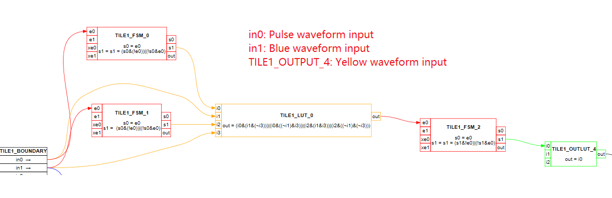
so the waveform of input and output should be like as below, which I did with F280049 launchpad: The waveform below are exactly what we want and are correct.

But in customer's system, the two input of the waveform are from their motor encoder signal, in this case, there have issue and sometimes output is wrong. in order to see if any noise of the two input, actually they use two CLB output to show the input signal, we can see that these signal that go to CLB module are clean, in most case the output are correct, but unfortunately sometimes the output is wrong as show in red arrow. we did not know why.

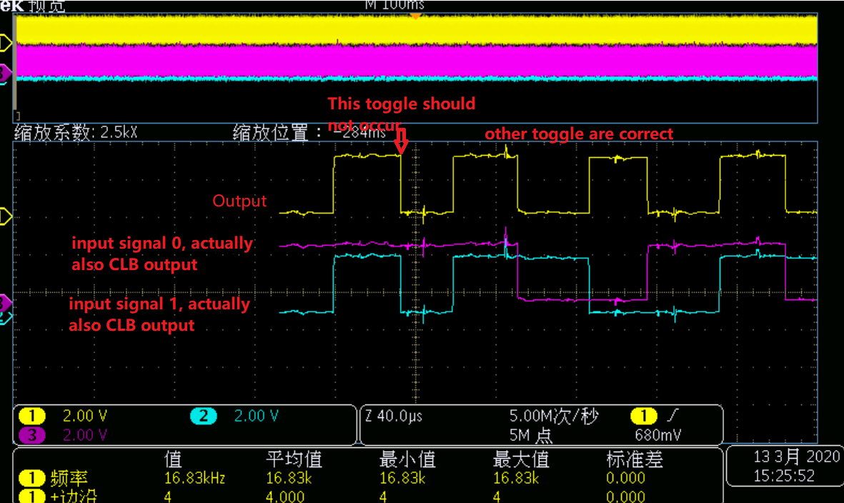
Further more, we also found more strange waveform that are output as below,   we think there may have some noise that influence the output, and try to add logic filter that configured by CLB to filtering the input two signals, but it did not work and remain have the issue.

any suggestion on how to fix this issue? Thanks.

  • Hi,

    Since you say that the logic is working as expected on LaunchPad but fails on customer system due to noise,
    Can you try to enable the input qualification logic in the GPIO?
    Monitor the input signal and observe the noise pulse width and set the GPIO qualification parameters accordingly.
    Typically, the encoder inputs may be noisy during transitions and it's best to have GPIO qualification enabled.
    If noise is indeed the source of the problem, this should fix it.
    Please try and let us know the results. 

  • Subrahmanya,

    Yes they do add input qualification logic in the GPIO, but have the same issue. as I mention, they also refer to the CLB example "clb_ex2_gpio_input_filter" to do the filtering, but still have the issue.

    And actually the waveform that Monitor are the input signal directly to CLB module because they use CLB output to GPIO to show the input signal.

  • Hi,

    Did you try to simply run the test "clb_ex2_gpio_input_filter" as it is? What is your observation?

  • Also, is this happening only when encoder input is used? What is the input you are using in the LaunchPad test?

  • refer to  "clb_ex2_gpio_input_filter" example and add filtering for the two input, the output of the filter will be send to FSM0 and FSM1, LUT0.

  • Yes only happen when encoder is used,

    The input on LaunchPad test  are the signal generated by PWM module and other CLB tile to generate a waveform that similar to encoder output.

  • Hi,

    Thanks for confirming, is it possible to first use GPIO filter (disable CLB filter) for debug purposes?
    It's not clear why the noise is propagating though you've the filter ON.
    What may be needed is to fine tune the filter settings to remove the noise.
    The qualification pulse width settings you've may not be enough to remove the noise.
    Can you capture the noise on the encoder input? That will give us some insight into the noise pulses.

  • Hi,

    Strong ZHANG said:
    The input on LaunchPad test  are the signal generated by PWM module and other CLB tile to generate a waveform that similar to encoder output.


    Since the noise issue is observed only when encoder is used, I wonder, the PWM based input generation is not replicating the noise as seen from encoder.
    Also, have you turned on the synchronizer on GPIO input?
    You can also turn on synchronization at CLB level, using CLB_INPUT_FILTER[SYNCn] bit. 

  • Subrahmanya,

    Yes customer turn on synchronization at CLB level and GPIO input.  they also find another issue when do more test.

    They are using F280049 Launchpad to do the test, the input signal is from motor encoder output. and in clb configuration, they use two tiles to connect this same signal, and just connect the BOUNDARY_In directly to BOUNDARY_Out, so the two output of the CLB tiles should be exactly the same as the input, but what strange is that the two output are different as below showed, one CLB output is the same as the input pulse, but the other is different.

    what is the reason about this? They also do the test by using two input of one CLB tiles, and the result show that still have this problem.

  • Hi Strong,

    Due to the synchronizers and latching of the input signals, there could be a slight variation (2-3 cycles) though you are using the same signal from input to output. If the variation is in that range of 2-3 cycles then it's expected due to this sync logic.
    But, if the variation is higher than that then there may be something else in the configuration or input/output settings causing this.
    What is the variation you've observed? how many ns?

  • Subrahmanya,

    The variation is about 10 us. The configuration in clb is simple, just connect the input to the CLB output without any logic calculation.

  • Subrahmanya,

    It is about 10us, and the configuration of CLB is simple, just connect the BOUNDARY_In directly to BOUNDARY_Out without  logic calculation.

  • Hi,
    If it is of the order of 10us then it is not synchronizer related delay. Synchronizer would only add few clock cycles, 10s of nano seconds only.
    I believe there must be something wrong in the configuration or the associated software.
    We have several example test cases with input output connections, glue logic etc., none of these exhibit such behavior.
    Please double check with examples, it'll also help us replicate quickly.