This thread has been locked.

If you have a related question, please click the "Ask a related question" button in the top right corner. The newly created question will be automatically linked to this question.

TIDM-1007: Start up code for bootstrap powered GaN daughter card

Part Number: TIDM-1007
Other Parts Discussed in Thread: LMG3410-HB-EVM,

Dear team,

We are trying to cost down our GaN daughter cards to make our solution more competitive by changing isolated power supply on LMG3410-HB-EVM to bootstrap power supply.

When starting up, each low-side LMG3410  should be driven by a PWM with low duty cycle to charge up bootstrap cap of high-side LMG3410 and avoid inductor current saturation. High-side LMG3410  can't be switched correctly until corresponding fault signal set high.

So any clues on how we should modify the firmware of TIDM-1007 for bootstrap powered GaN daughter cards?

Thanks and Best Regards,

Charles Zhao

  • Charles,

    Please see the state machine of the PWM

    pwmSwState_normalOperation:
    
                // wait for positive zero crossing i.e. state 6
                if(acSine < threshold_PZC2  && acSinePrev<0)
                {
                    pwm_SwState.enum_pwmSwState=pwmSwState_positiveZeroCrossing1;
    
                    dutyPU=0.004;
    
                    AQ_SW_FORCE_PWMxA_LOW_PWMxB_LOW(LOW_FREQ_PWM_BASE);
    
                    SET_PWM_DBRED(HIGH_FREQ_PWM1_BASE,PFC_PWM_PERIOD);
                    SET_PWM_DBFED(HIGH_FREQ_PWM1_BASE,PFC_PWM_PERIOD);
    
                    SET_PWM_DBRED(HIGH_FREQ_PWM2_BASE,PFC_PWM_PERIOD);
                    SET_PWM_DBFED(HIGH_FREQ_PWM2_BASE,PFC_PWM_PERIOD);
    
                    SET_PWM_DBRED(HIGH_FREQ_PWM3_BASE,PFC_PWM_PERIOD);
                    SET_PWM_DBFED(HIGH_FREQ_PWM3_BASE,PFC_PWM_PERIOD);
    
                    gi.i10=0;
                    gi.i6=1;
                    gi_out=0;
    
                    clearPWMTripFlags(LOW_FREQ_PWM_BASE);
                    clearPWMTripFlags(HIGH_FREQ_PWM1_BASE);
                    clearPWMTripFlags(HIGH_FREQ_PWM2_BASE);
                    clearPWMTripFlags(HIGH_FREQ_PWM3_BASE);
    
                    ac_cur_ref_inst=0.00;
                    ac_cur_ref_inst=0.00;
                    closeGiLoop=1;
                    closeGvLoop=1;
    
                }

    Also see

    http://www.ti.com/lit/ug/tidud61b/tidud61b.pdf

    sec 2.4.4

    During startup, the lower FET switch is turned ON before upper switch , and it is soft started. so hopefully you do not need to do anything. 

  • Hi Manish,

    Thanks for your reply!

    I think the only problem left behind is that the voltage of bootstrap cap need to be charged higher than UVLO during soft-start. I'll put up some test on it.

    Thanks and Best Regards,

    Charles Zhao

  • Hi Manish,

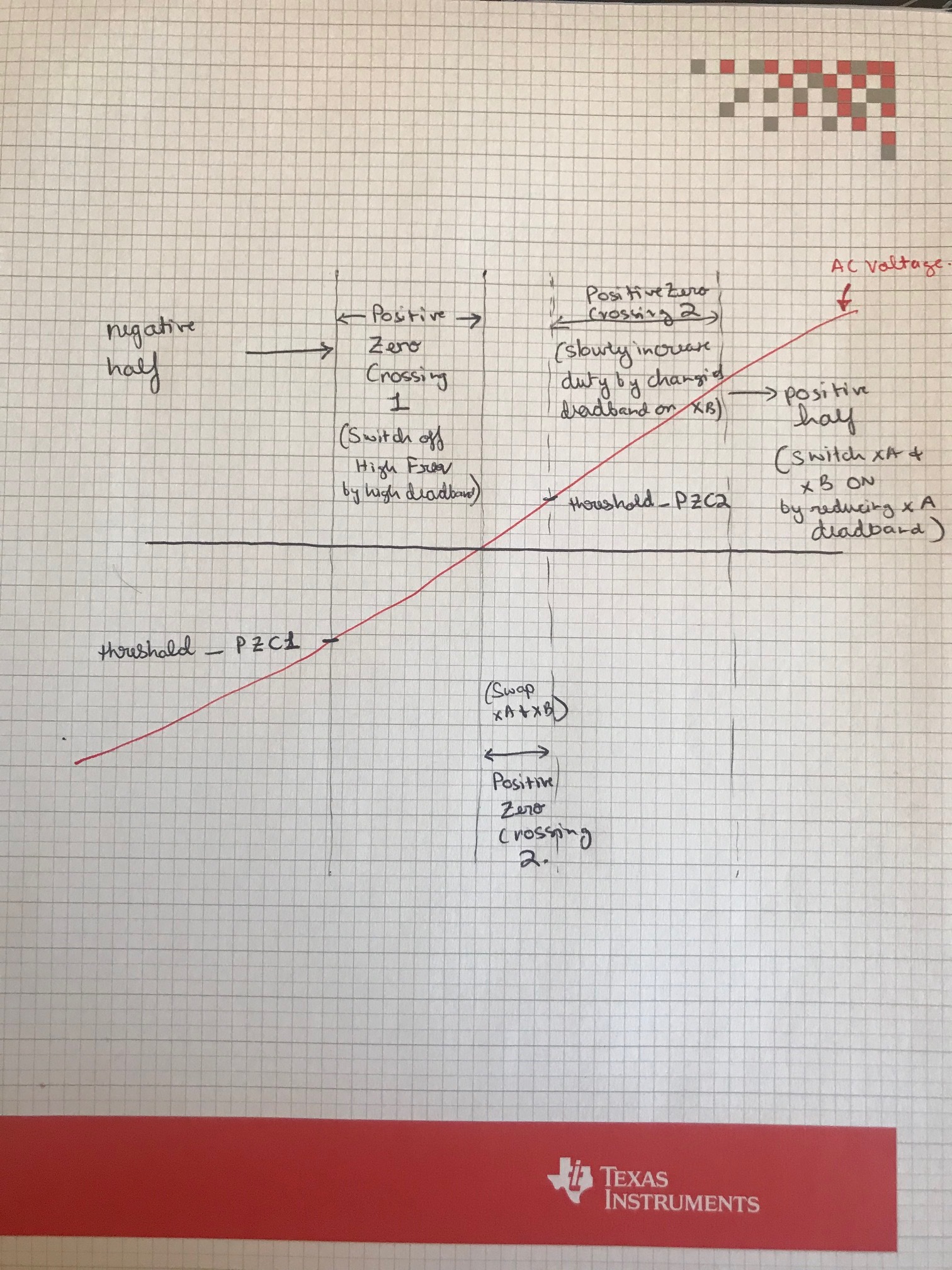
    As I look into state machine code of the PWM control, I get a bit confused. According to SLYT650 , the soft-start sequence of zero-crossing should be:

    (1) All switches off => (2) Main FET soft-start => (3) Low freq FET on and sync FET soft-start => (4) Normal operation

    Take positive zero-crossing for an example. Based on my understanding, positiveZeroCrossing1 and positiveZeroCrossing2 seems to be the same for (1) and main FET starts soft-switching during positiveZeroCrossing3, which doesn't fit the soft-start sequence.

    So would you please share some more comments on how these 3 zero-crossing states work? I must get it wrong somewhere.

    Thanks a lot!

    Best Regards,

    Charles Zhao

  • Hopefully the above diagram explains it a little better, during PZC3 state only the Low side high freq switch is ON. we did modify it slightly from the original proposal in the app note you referred to. 

    -Manish 

  • Hi Manish,

    This diagram really helps a lot. I can fully understand the state machine now.

    Thanks so much for all your time and help!

    Best Regards,

    Charles Zhao