This thread has been locked.

If you have a related question, please click the "Ask a related question" button in the top right corner. The newly created question will be automatically linked to this question.

LAUNCHXL-F280049C: PWM in STATE_RATEDFLUX_OL

Guru 55913 points
Part Number: LAUNCHXL-F280049C

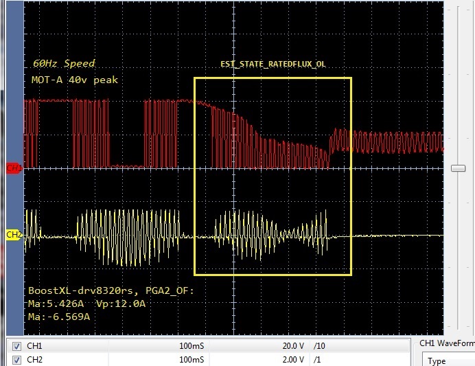
Testing BootXL-DRV8320rs with full CMPSS DC bidirectional current protection engaged to keep rotor moving, until unsafe current conditions.

The PWM droops DC power supply as EST_STATE_RATEDFLUX_OL starts up after constant speed and current ramp stabilizes.

2. Dumb question being should CH1  voltage drop on purpose or is the current load to much for the state to finish?

3. If it should not drop voltage (yellow box) then how does reduced current CH2 cause sudden DC trip zone fault? 

4. How on earth did motor ID=true @20Hz with rotor stalled, then run without error for online lab5? Not so important unless the DC comparators are working as they should and ID process Rated_Flux step trips OC faults at 20Hz. 

5. Why do the user parameters entered into user.h not accelerate the rotor in lab 5 when launched with use user.h parameters flag = true? All that occurs is the rotor slowly rolls clock wise as if the trajectory target speed parameter is missing. This happens on boostXL and our custom DC inverter and it seems SDK requires certain parameter values gathered during motor ID process that go missing when CCS debug secession ends. Lab 13 has the same behavior and only accelerates the rotor up to target Hz after motor ID=true after lab5 enters OnLine state. Seemingly the SDK should save a lot more than user.h motor vars in a flash parameter block for later debug sessions. Lab 5 is loaded into flash memory as instructed via lab user guide.

I plead totally bamboozled by this behavior, lol. Be safe and keep some distance from others!


  • I don't think the motor is running properly with your project on the board. What changes did you do on the example lab05? And did you add any loading on the motor during the identification process? You must do the motor identification under a no-load or light load test.

    As we replied to the other threads you posted before, we can't repeat the problems you mentioned. Could you please provide a more detailed description of the operation process if you have any questions? 

  • Yanming Luo said:
    I don't think the motor is running properly with your project on the board

    That much is obvious but only during Rated Flux is there any issues on all motors tested. Attempting to use user.h parameters to control the motor after ID=true does not work in a new CCS debug secession as you instructed to try. This means the required motor parameter to accelerate rotor are not simply kept in user.h  and motor ID must be run every time. There are areas in the SDK code that need further work! We should be able to run motor via parameters taken from user.h and launch CCS debug to run lab5 or greater to accelerate motor with parameter flags shown below. The problem seems to be the velocity trajectory values are cleared when ever CCS debug session is terminated.

    So user.h parameter list is missing crucial motor.vars needed to accelerate rotor to new secession Online trajectory target Hz. Seemingly SDK sets a very bad example of what not to do to make any motor run via SPV.  Seemingly overly complicated code has fixed User value locked 10Hz (lab5) when low inductance motors require >10Hz to properly ID the rated flux without stalled rotor. Rated flux can not properly from a stalled 20Hz rotor with DCA/B is configured to trip ePWM faults to avoid burning the Boost kit! The SDK limited OV protection was to rely Tz2 alone can not protect the custom DC inverter >60v per-production testing using launchXl >50A peaks. Yet CH1 testing 40V with DC trips enabled filer counts (+/-3648) and drop (CH1) eventually trips OC fault (CH2) well before Tz2 ever reports trouble. Seemingly this is a good thing as it protects ePWM module (randomly) burning BoostXL as it did the first time.

    So is 40v DC power supply to low current rating (10A) in this 60Hz test?

        /* Use ID'd motor settings from user.h */
        motorVars.flagEnableUserParams = true;
        /* No Motor ID, use previous motor.vars from user.h */
        userParams.flag_bypassMotorId = true;

    Yanming Luo said:
    What changes did you do on the example lab05?

    Only user.h motor parameters to get rotor to 60Hz 42vdc <9A. It can run 300 rpm +24vdc (5.4A) steady state via 6 step (FOC) commutation! 

    Yanming Luo said:
    And did you add any loading on the motor during the identification process?

    Unloaded 60Hz rotor speed upon entering Rated flux. Note the locked rotor flag was set true (labs.h) and this is SPM, not ACIM. 

    Yanming Luo said:
    Could you please provide a more detailed description of the operation process if you have any questions? 

    How much more detail do you need (scope capture is worth 1000 words). Rated Flux drags down 40v 10A power supply to 17v, is that intentional?

    Should that voltage drop CH2 be occurring? How can anyone know any different as there is no circuit analysis for the PWM voltages during Rated Flux?

  • The odd part was FW dragged down 40v power supply to 17v just like Rated Flux is doing. The only way the rotor ever >550Hz was after motor ID=true (20Hz stalled rotor flux) captured. Then Labs5/13 could accelerate rotor >60Hz via labs5/13 in same debug session. Never tried to run motor >20Hz after terminating CCS debug for later run with the updated values placed in user.h. 

    Unless we disable DCA/B trips, stalled rotor flux capture can not be easily achieved. After boost burn don't want to trust stalled rotor method, noted unworthy <10µH inductance (SPRUHJ1H).

    This is the DCA/B ePWM (OSHT) trip point math for the filter component, with or without ASYNCH path OR'd makes no difference to Rated Flux trip point.

    +/-3648 * 820µV =2.99136v / 140mV/A = 21.37A DCA/B trip point.

    Above capture CH2  current probe PGA_OUT via PGA2_OF, math indicates 140mV/A via 7mohm shunt (x12 gain) is <22A 1/2 ADC FS.

    Note CMPSSx DC is near top of PTP trip point of 1/2 42A Peak. Seems to infer 7mohm shunt size being twice what should be for DC threshold set >22A. The NexFET datasheet shows 40A winding current infers PTP value, not Peak. Both half cycles of current (measure) sine wave do not occur at the same time. So ADC could have 80A Peak FS for 3.5mohm shunt that any 1/2 cycle can 40A PTP better serve DC filter (1.68v<3.1v) trip values.

    One problem being labs.h had forced DCA/B 2048 shadow right at threshold of PGA_OUT (1.68v). Perhaps the designer of SDK became confused seeing unsigned integers to evaluate a signed and negative value count for DC filter values (0v<1.68v).  Signed negative integers makes ePWM trips H/L sources opposite D/Q, R/S toggle states via MUX translation of latch events, since DCB must trip from inverted filter events <1.68v. Trick is to make DCA/B event 1A/1B (OSHT) not falsely set high latch status, versus quiet Q toggle trip via DCB integer count values.  Otherwise high or low side CMPSS latch status remains set after SW clear thus tripping fault when calibrate Offset runs. 

  • To be frank, I am confused about this thread you posted, I am difficult to get what's the finial questions you want to discuss.

    Are you using the TI's EVM board or your own board? As we replied to other threads you posted, can you make sure that the current and voltage sensing signals are good for the motor drive if you are using your own inverter board?

    There are only lab05 supports motor identification, and you should set the correct identification variables according to your motor. Please post your user.h if possible.

    #define USER_MOTOR_RES_EST_CURRENT_A (2.0)
    #define USER_MOTOR_IND_EST_CURRENT_A (-1.5)
    #define USER_MOTOR_MAX_CURRENT_A (6.0)
    #define USER_MOTOR_FLUX_EXC_FREQ_Hz (40.0)

    The DACA and DACB are set to ~2048 that provide the ~1.65V offset to the PGA based on the current sensing circuit of the TI's EVM, the setting value needs to be calculated according to the external sensing circuit and the gains of the PGA. Please have a look at chapter 14 of F2800x TRM if you want to understand more.

    In the example lab, you just need to change the motorVars.dacValH and motorVars.dacValL to set the internal DAC value of on-chip comparator for current protection.