This thread has been locked.

If you have a related question, please click the "Ask a related question" button in the top right corner. The newly created question will be automatically linked to this question.

TMS320F28377S: CAN Configuration Issue

Part Number: TMS320F28377S
Other Parts Discussed in Thread: C2000WARE

I am trying to confirm my CAN configuration via a watch window and it doesn't appear that I am updating any registers or memory.

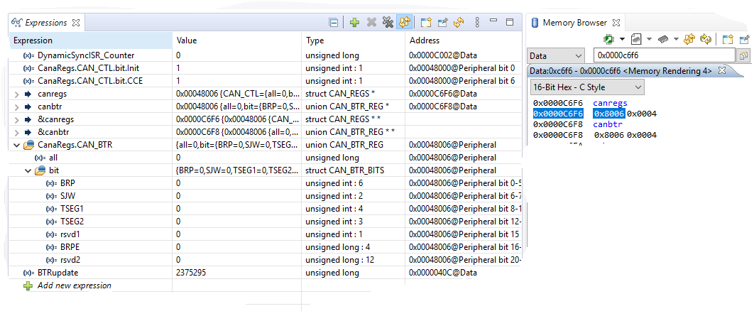
I am configuring CANA in a similar manner to that done in the C200ware example can_loopback_bitfields_cpu01.  I am setting both the CAN_CTL Init and CCE bits, and can see this update on the watch window. When I write to the CAN_BTR register I see no change in the register as observed in the watch window.  None of the other registers appear to be getting set either, and I see no change in the CANA message RAM when I observe it through the Memory Browser.  

I have also tried setting CAN_BTR in the manner used in the C200ware exmaple can_external_transmit_cpu01 and have observed similar results.  

What am I doing wrong, or what have I missed?

Thanks in advance for any insight.

  • Hi Andrew,

    If there is a way that you can migrate your application to use the driverlib functions and examples (in C2000Ware root directory/driverlib/f2837xs/examples/cpu1/can/…), I highly encourage you to do that.  The bitfield functions and examples are deprecated and there is not a lot of support.  I suspect that what you are seeing is a result of the register mapping with the older bitfield structures.


    Anyway, here is a quick suggestion to see if it is indeed a register display mapping issue (but before going the steps below, CCE and Init bits in CAN_CTL have to be set in order for CAN_BTR register to be writeable):

        - Add this declaration: struct CAN_REGS *canregs;

        - add this in your code: canregs = &CanaRegs.CAN_BTR;

    The above code snippet just assigns the address of CAN_BTR to variable canregs.  In the expressions window, add canregs.  The value of canregs address will be displayed in the expressions window after executing the above codes.  Go to the memory browser and type in the address of canregs.  See if the memory window displays the updated values of CAN_BTR when you are writing the bit timing parameters.  Give this a shot and let me know.

    Regards,

    Joseph

  • Joseph,

    I've made these declarations:

    volatile struct CAN_REGS        *canregs;
    volatile union CAN_BTR_REG *canbtr;

    note:  I added *canbtr as insurance because I was getting a compiler warning that type "volatiule union CAN_BTR_REG cannot be assigned to an entity of type "volatile struct CAN_REGS"; it worked as planned however.  

    and implemented these lines in my code:

    canregs = &CanaRegs.CAN_BTR;
    canbtr    = &CanaRegs.CAN_BTR;

    volatile uint32 BTRupdate =  (uint32)BRP_VAL                \
                                              + ((uint32)SJW_VAL<<6)        \
                                              + ((uint32)TSEG1_VAL<<8)    \
                                              + ((uint32)TSEG2_VAL<<12)  \
                                              + ((uint32)BRPE_VAL<<16);


    CanaRegs.CAN_BTR.all = BTRupdate;

    The expression and memory browser windows after execution of the above lines are shown below:

    Note that both canregs and canbtr are set to address 0x00048006, which is NOT the CAN_BTR address, which should be 0x00048000C.  Is this the problem?

  • Hi Andrew,

    Yes, that is the issue with CAN bitfield headers as register view is misleading.  Register implementation is every other 32-bit word but not displayed properly in register view.  In driverlib, these offsets are predefined in inc/hw_can.h:

    //*****************************************************************************
    //
    // The following are defines for the CAN register offsets
    //
    //*****************************************************************************
    #define CAN_O_CTL 0x0U // CAN Control Register
    #define CAN_O_ES 0x4U // Error and Status Register
    #define CAN_O_ERRC 0x8U // Error Counter Register
    #define CAN_O_BTR 0xCU // Bit Timing Register
    #define CAN_O_INT 0x10U // Interrupt Register
    #define CAN_O_TEST 0x14U // Test Register
    #define CAN_O_PERR 0x1CU // CAN Parity Error Code
    // Register
    #define CAN_O_RAM_INIT 0x40U // CAN RAM Initialization

    :

    :...etc...

    Regards,

    Joseph

  • Joseph,

    Thanks for the info, a lot makes sense now.  

    I've had success programming registers like this:

    union   CAN_BTR_REG         *pCAN_BTR;

    Can.A.pCAN_BTR          = (union    CAN_BTR_REG         *)(CANA_BASE + CAN_O_BTR);

    This allows me to access the bitfields, at least for debug purposes.  I've noticed writes only seem to reliably be implemented when done as a 32 bit word, does that make sense?

    One more question.  Are Mailboxes 1 and 2 restricted to transmit only? I can see that the message RAM for Mailbox 0 is properly configured when I configure it as TX, but if I the configure Mailbox 1 for Rx I don't get expected results (the RAM ges completely zero'd).

    Thanks,

    Andy

  • Andrew,

    All 32 mailboxes are configurable as transmit or receive.  None of the mailboxes are exclusive to transmit or receive only.

    Regards,

    Joseph