This thread has been locked.

If you have a related question, please click the "Ask a related question" button in the top right corner. The newly created question will be automatically linked to this question.

TMDSCNCD280049C: The device won't wake up after powered on if a modified linker command file is utilized.

Part Number: TMDSCNCD280049C
Other Parts Discussed in Thread: C2000WARE, TMDXIDDK379D

Hi Champs,

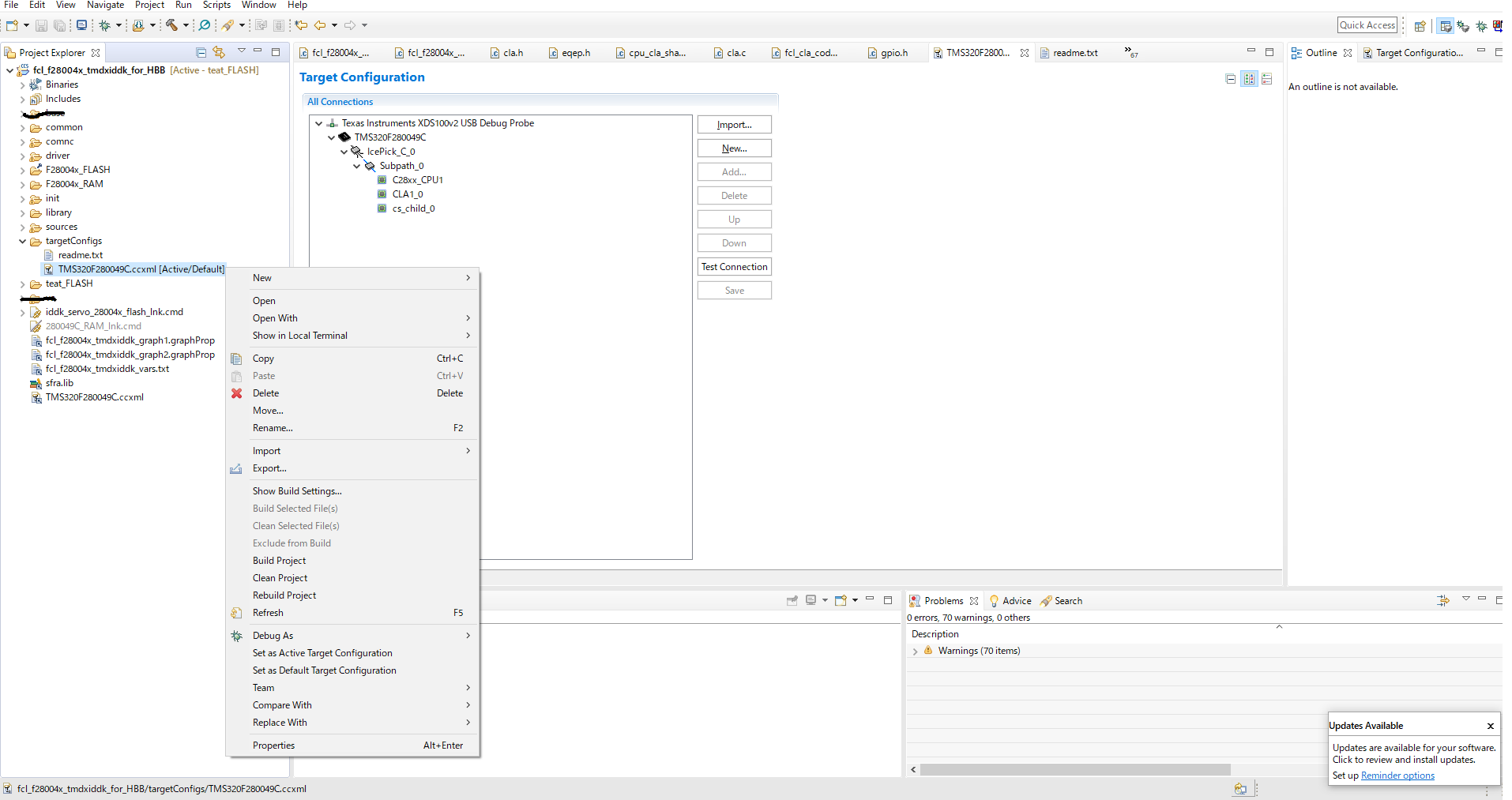
A customer has been facing a problem that the program does not work with a linked command file named “iddk_servo_2837x_flash_lnk_cpu1.cmd” as attached.
The file was modified by the customer.

They have confirmed that the LED sample code works with "28004x_generic_flash_lnk.cmd" with no problem.
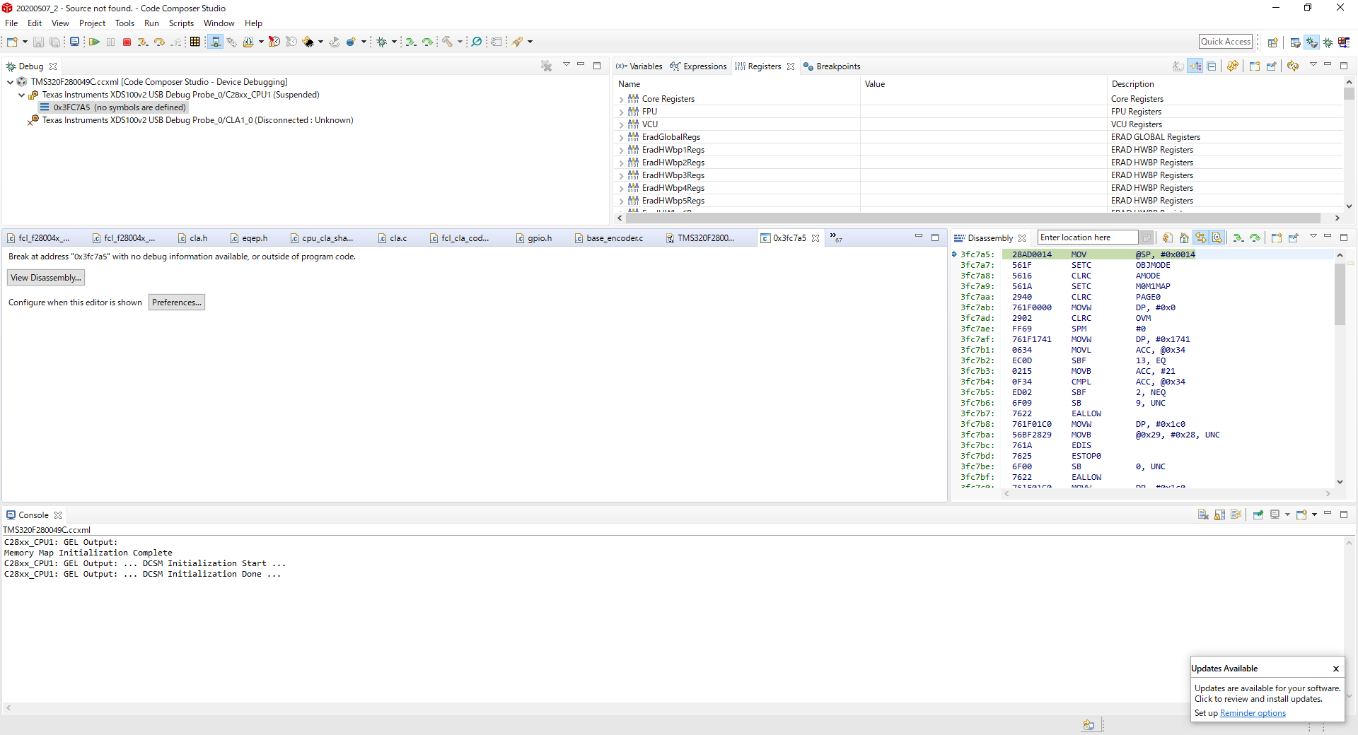
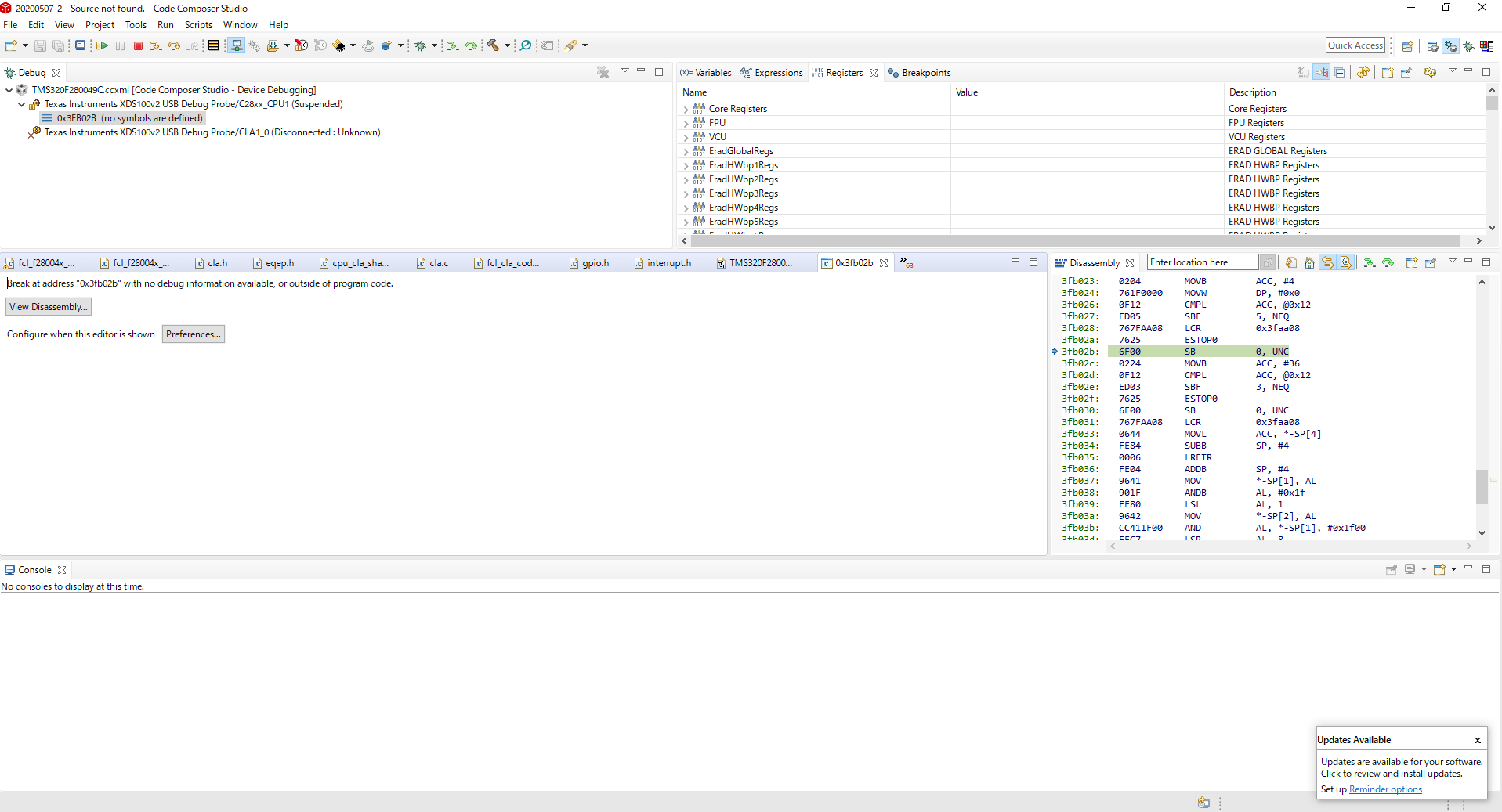
The failure condition with “iddk_servo_2837x_flash_lnk_cpu1.txt” is that the program does not work after powered on.
With CCS debug -> RUN works fine.

It seems that their .cmd causes the problem.
Could you please investigate the contents of the attached file?

Thank you in advance for your time check.
Best regards,
Hitoshi

iddk_servo_2837x_flash_lnk_cpu1.txt
//#############################################################################
//
// FILE:    iddk_servo_2837x_flash_lnk_cpu1.cmd
//
//#############################################################################
// $TI Release: MotorControl SDK v2.01.00.00 $
// $Release Date: Mon Nov 11 15:18:12 CST 2019 $
// $Copyright:
// Copyright (C) 2017-2019 Texas Instruments Incorporated
//
//     http://www.ti.com/ ALL RIGHTS RESERVED
// $
//#############################################################################
// In addition to this memory linker command file,
// add the header linker command file directly to the project.
// The header linker command file is required to link the
// peripheral structures to the proper locations within
// the memory map.
//
// For BIOS applications add:      F28004x_Headers_BIOS.cmd
// For nonBIOS applications add:   F28004x_Headers_nonBIOS.cmd
//
// The user must define CLA_C in the project linker settings if using the
// CLA C compiler
// Project Properties -> C2000 Linker -> Advanced Options -> Command File
// Preprocessing -> --define
#ifdef CLA_C
// Define a size for the CLA scratchpad area that will be used
// by the CLA compiler for local symbols and temps
// Also force references to the special symbols that mark the
// scratchpad are.
CLA_SCRATCHPAD_SIZE = 0x100;
--undef_sym=__cla_scratchpad_end
--undef_sym=__cla_scratchpad_start
#endif //CLA_C


MEMORY
{
   /* BEGIN is used for the "boot to SARAM" bootloader mode   */
   RESET             : origin = 0x3FFFC0, length = 0x000002

   BEGIN             : origin = 0x080000, length = 0x000002
/*   FLASH_BANK0_SEC0  : origin = 0x080002, length = 0x000FFE*/	/* on-chip Flash */
/*   FLASH_BANK0_SEC1  : origin = 0x081000, length = 0x001000*/	/* on-chip Flash */
/*   FLASH_BANK0_SEC2  : origin = 0x082000, length = 0x001000*/	/* on-chip Flash */
/*   FLASH_BANK0_SEC3  : origin = 0x083000, length = 0x001000*/	/* on-chip Flash */
/*   FLASH_BANK0_SEC4  : origin = 0x084000, length = 0x001000*/	/* on-chip Flash */
/*   FLASH_BANK0_SEC5  : origin = 0x085000, length = 0x001000*/	/* on-chip Flash */
/*   FLASH_BANK0_SEC6  : origin = 0x086000, length = 0x001000*/	/* on-chip Flash */
/*   FLASH_BANK0_SEC7  : origin = 0x087000, length = 0x001000*/	/* on-chip Flash */
//   FLASH_BANK0_SEC8  : origin = 0x088000, length = 0x001000	/* on-chip Flash */
/*   FLASH_BANK0_SEC9  : origin = 0x089000, length = 0x001000*/	/* on-chip Flash */
/*   FLASH_BANK0_SEC10 : origin = 0x08A000, length = 0x001000*/	/* on-chip Flash */
   FLASH_BANK0_SEC0_10  : origin = 0x080002, length = 0x00AFFE	/* on-chip Flash */
/*   FLASH_BANK0_SEC11 : origin = 0x08B000, length = 0x001000*/	/* on-chip Flash */
/*   FLASH_BANK0_SEC12 : origin = 0x08C000, length = 0x001000*/	/* on-chip Flash */
/*   FLASH_BANK0_SEC13 : origin = 0x08D000, length = 0x001000*/	/* on-chip Flash */
/*   FLASH_BANK0_SEC14 : origin = 0x08E000, length = 0x001000*/	/* on-chip Flash */
   FLASH_BANK0_SEC11_14  : origin = 0x08B000, length = 0x004000	/* on-chip Flash */
   FLASH_BANK0_SEC15 : origin = 0x08F000, length = 0x001000	/* on-chip Flash */

   /* BANK 1 */
   FLASH_BANK1_SEC0  : origin = 0x090000, length = 0x001000	/* on-chip Flash */
   FLASH_BANK1_SEC1  : origin = 0x091000, length = 0x001000	/* on-chip Flash */
   FLASH_BANK1_SEC2  : origin = 0x092000, length = 0x001000	/* on-chip Flash */
   FLASH_BANK1_SEC3  : origin = 0x093000, length = 0x001000	/* on-chip Flash */
   FLASH_BANK1_SEC4  : origin = 0x094000, length = 0x001000	/* on-chip Flash */
   FLASH_BANK1_SEC5  : origin = 0x095000, length = 0x001000	/* on-chip Flash */
   FLASH_BANK1_SEC6  : origin = 0x096000, length = 0x001000	/* on-chip Flash */
   FLASH_BANK1_SEC7  : origin = 0x097000, length = 0x001000	/* on-chip Flash */
   FLASH_BANK1_SEC8  : origin = 0x098000, length = 0x001000	/* on-chip Flash */
   FLASH_BANK1_SEC9  : origin = 0x099000, length = 0x001000	/* on-chip Flash */
   FLASH_BANK1_SEC10 : origin = 0x09A000, length = 0x001000	/* on-chip Flash */
   FLASH_BANK1_SEC11 : origin = 0x09B000, length = 0x001000	/* on-chip Flash */
   FLASH_BANK1_SEC12 : origin = 0x09C000, length = 0x001000	/* on-chip Flash */
   FLASH_BANK1_SEC13 : origin = 0x09D000, length = 0x001000	/* on-chip Flash */
   FLASH_BANK1_SEC14 : origin = 0x09E000, length = 0x001000	/* on-chip Flash */
   FLASH_BANK1_SEC15 : origin = 0x09F000, length = 0x001000	/* on-chip Flash */

   BOOTROM     		: origin = 0x3FF27C, length = 0x000D44

   BOOT_RSVD   		: origin = 0x000002, length = 0x0000F3     /* Part of M0, BOOT rom will use this for stack */
   RAMM0       		: origin = 0x0000F5, length = 0x00030B
   RAMM1       		: origin = 0x000400, length = 0x000400     /* on-chip RAM block M1 */

   CLA1_MSGRAMLOW  	: origin = 0x001480, length = 0x000080
   CLA1_MSGRAMHIGH 	: origin = 0x001500, length = 0x000080

/* RAMLS0           : origin = 0x008000, length = 0x000800 */
/* RAMLS1           : origin = 0x008800, length = 0x000800 */
   RAMLS0_1         : origin = 0x008000, length = 0x001000
   RAMLS2           : origin = 0x009000, length = 0x000800
   RAMLS3           : origin = 0x009800, length = 0x000800
   RAMLS4           : origin = 0x00A000, length = 0x000800
   RAMLS5           : origin = 0x00A800, length = 0x000800
   RAMLS6           : origin = 0x00B000, length = 0x000800
   RAMLS7           : origin = 0x00B800, length = 0x000800

   RAMGS0           : origin = 0x00C000, length = 0x002000
   RAMGS1           : origin = 0x00E000, length = 0x002000
/*   RAMGS2           : origin = 0x010000, length = 0x002000*/
/*   RAMGS3           : origin = 0x012000, length = 0x002000*/
   RAMGS2_3           : origin = 0x010000, length = 0x004000
}


SECTIONS
{
   /* Setup for "boot to SARAM" mode:
      The codestart section (found in DSP28_CodeStartBranch.asm)
      re-directs execution to the start of user code.  */
   codestart        : > BEGIN
//   .text            : >> FLASH_BANK0_SEC0 | FLASH_BANK0_SEC1 | FLASH_BANK0_SEC2
   .text            : >> FLASH_BANK0_SEC0_10, ALIGN(4) /* , ALIGN(4)*/
//   .cinit           : > FLASH_BANK0_SEC3
//   .switch          : > FLASH_BANK0_SEC3
   .cinit           : > FLASH_BANK0_SEC15, ALIGN(4) /* , ALIGN(4)*/
   .switch          : > FLASH_BANK0_SEC15
   .reset           : > RESET,	TYPE = DSECT /* not used, */
   .stack           : > RAMM1

#if defined(__TI_EABI__)
//   .init_array      : > FLASH_BANK0_SEC3, ALIGN(4)
   .init_array      : > FLASH_BANK0_SEC15, ALIGN(4)
//   .bss             : > RAMGS3
//   .bss:output      : > RAMGS3
//   .bss:cio         : > RAMGS3
//   .data            : > RAMGS3
//   .sysmem          : > RAMGS3
   .bss             : > RAMGS2_3, ALIGN(4) /* , ALIGN(4)*/
   .bss:output      : > RAMGS2_3, ALIGN(4) /* , ALIGN(4)*/
   .bss:cio         : > RAMGS2_3, ALIGN(4) /* , ALIGN(4)*/
   .data            : > RAMGS2_3, ALIGN(4) /* , ALIGN(4)*/
   .sysmem          : > RAMGS2_3, ALIGN(4) /* , ALIGN(4)*/
   /* Initalized sections go in Flash */
//   .const           : > FLASH_BANK0_SEC3, ALIGN(4)
   .const           : > FLASH_BANK0_SEC11_14 , ALIGN(4)
#else
   .pinit           : > FLASH_BANK0_SEC15,   PAGE = 0, ALIGN(4)
//   .ebss            : > RAMGS3,    			PAGE = 1
//   .esysmem         : > RAMGS3,       		PAGE = 1
//   .cio             : > RAMGS3,       		PAGE = 1
   .ebss            : > RAMGS2_3,    			PAGE = 1
   .esysmem         : > RAMGS2_3,       		PAGE = 1
   .cio             : > RAMGS2_3,       		PAGE = 1
   .econst          : > FLASH_BANK0_SEC15,   PAGE = 0, ALIGN(4)
#endif

#if defined(__TI_EABI__)
    .TI.ramfunc : {
                    --library = PM_tformat_lib_f28004x.lib (.text)
//                   } LOAD = FLASH_BANK0_SEC4,
                     } LOAD = FLASH_BANK1_SEC0,
                     RUN = RAMLS0_1,
                     LOAD_START(RamfuncsLoadStart),
                     LOAD_SIZE(RamfuncsLoadSize),
                     LOAD_END(RamfuncsLoadEnd),
                     RUN_START(RamfuncsRunStart),
                     RUN_SIZE(RamfuncsRunSize),
                     RUN_END(RamfuncsRunEnd),
					 ALIGN(4)
#else
    .TI.ramfunc : {
                    --library = PM_tformat_lib_f28004x.lib (.text)
//                   } LOAD = FLASH_BANK0_SEC4,
                     } LOAD = FLASH_BANK1_SEC0,
                     RUN = RAMLS0_1,
                     LOAD_START(RamfuncsLoadStart),
                     LOAD_SIZE(RamfuncsLoadSize),
                     LOAD_END(RamfuncsLoadEnd),
                     RUN_START(RamfuncsRunStart),
                     RUN_SIZE(RamfuncsRunSize),
                     RUN_END(RamfuncsRunEnd),
					 PAGE = 0, ALIGN(4)
#endif

#if defined(__TI_EABI__)
    /* CLA specific sections */
//   Cla1Prog         : LOAD = FLASH_BANK0_SEC4,
   Cla1Prog         : LOAD = FLASH_BANK1_SEC0,
                      RUN = RAMLS4 | RAMLS5,
                      LOAD_START(Cla1funcsLoadStart),
                      LOAD_END(Cla1funcsLoadEnd),
                      RUN_START(Cla1funcsRunStart),
                      LOAD_SIZE(Cla1funcsLoadSize),
                      ALIGN(4)
#else
    /* CLA specific sections */
//   Cla1Prog         : LOAD = FLASH_BANK0_SEC4,
     Cla1Prog         : LOAD = FLASH_BANK1_SEC0,
                      RUN = RAMLS4 | RAMLS5,
                      LOAD_START(Cla1funcsLoadStart),
                      LOAD_END(Cla1funcsLoadEnd),
                      RUN_START(Cla1funcsRunStart),
                      LOAD_SIZE(Cla1funcsLoadSize),
                      PAGE = 0, AALIGN(4)
#endif

   ClaData          : > RAMLS3, ALIGN=2

   Cla1ToCpuMsgRAM  : > CLA1_MSGRAMLOW
   CpuToCla1MsgRAM  : > CLA1_MSGRAMHIGH

    /* SFRA specific sections */
//   SFRA_F32_Data    : > RAMGS3, ALIGN = 64
     SFRA_F32_Data    : > RAMGS2_3, ALIGN = 64
   
#ifdef CLA_C
  /* CLA C compiler sections */
   //
   // Must be allocated to memory the CLA has write access to
   //
   CLAscratch       :
                        { *.obj(CLAscratch)
                        . += CLA_SCRATCHPAD_SIZE;
                        *.obj(CLAscratch_end) } >  RAMLS2,  ALIGN=2

   .scratchpad      : > RAMLS2
   .bss_cla		    : > RAMLS2
//   .const_cla	    :  LOAD = FLASH_BANK0_SEC3,
    .const_cla	    :  LOAD = FLASH_BANK0_SEC15,
                       RUN = RAMLS4 | RAMLS5,
                       RUN_START(Cla1ConstRunStart),
                       LOAD_START(Cla1ConstLoadStart),
                       LOAD_SIZE(Cla1ConstLoadSize),
  					   ALIGN(2)
#endif //CLA_C
}

//===========================================================================
// End of file.
//===========================================================================

  • Can you elaborate on what they mean by "does not work"? Can they tell if it is even reaching main()? Do they have the CodeStartBranch.asm (or a custom equivalent) in their project?

    I didn't spot anything concerning in the cmd file. Do they mind sharing their .map file too?

    Whitney

  • Hi Whitney,

    Thank you so much for your check for the .CMD.
    Could you please wait for a couple of days to get the map file.

    Best regards,
    Hitoshi 

  • Hi Whitney,

    Here is the map file as attached.
    I would appreciate if you could kindly look into it and let me know any findings.

    Thank you for your investigation.
    Best regards,
    Hitoshifcl_f28004x_tmdxiddk.txt

  • Thank you for the .map file. I'm still not seeing anything obviously wrong. Can you get an answer to my earlier question--in what way is it failing? Is it reaching main() or failing to boot? Can they maybe blink an LED or toggle a pin at strategic points in the code to try to determine where it is breaking?

    Whitney

  • Hi Whitney,

    Thank you for your kind investigation.
    According to the customer, the program does not run after powered on.
    For the debug, if the XDS is connected to the board and the load the code from CCS, it can run with no problem.
    However, after the XDS is disconnected and powered the board on again, the program does not wake up. 
    No LED blinking, etc.
    They hardly check if main() is called properly or not.

    They have tested with our LED blinking example code and the program runs fine.
    Therefore, they thought the linker command file setting was incorrect.

    I think it is better to re-create the linker command file by using the file in our LED example and test with it from a simple code.
    If you have any recommendations, it would be very helpful.

    Thank you again and best regards,
    HItoshi


  • When they run the LED blinking example, are they using the Flash build configuration or RAM configuration? I'm wondering if maybe they have the boot mode pins set to boot from RAM instead of Flash?

    One thing they can try is to create a build configuration in CCS and bypass the GEL file, so that when they reconnect to the device after it has failed to boot, they can do so without the GEL file resetting it. This will allow them to look at where the the code was stuck. If the PC shows they're in boot ROM they can try load the ROM symbols (in C2000Ware under libraries/boot_rom/) to get an idea what happened.

    Whitney

  • Hi Whitney,

    The customer will debug their code accordingly.
    If they have any further questions, will issue the post again onto e2e.

    Thank you for your kind checking for .CMD and .MAP files.
    Best regards,
    Hitoshi

  • Hi Whitney,

    I am currently debugging.

    I have bypassed the GEL file (C28xx_CPU1), but I can't see where the code is stuck.

    Can you tell me how to find out where the code is stuck?

    Best,Regards

    Rui

  • Once you've connected to the device, what do you see in the CCS debug perspective? You should at least be able to look at the program counter and find out what code it is trying to execute. What is the address?

    Have you tried adding the symbols for the boot ROM and your application for further details?

    Whitney

  • Thank you for your reply.

    The CCS Debug Perspective shows:
    ・Debug
     fcl_f28004x_tmdxiddk[Code Composer Studio-Device Debugging]
       Texas Instruments XDS100v2 USB Debug Probe/CLA1_0(Disconnected:Unknown)

    ・Disassembly
    ・・・・・・|・・・

    The address and program counter are not displayed, what window should I look at in the debug perspective?

  • In your screen capture you aren't actually connected to the device. You need to hit the connect button on the toolbar. Once it's connected, you should be able to see the address in the Debug panel, but you can also open up the Core Registers section in the Registers panel and find the PC in there.

    Whitney

  • Thank you for your reply.

    When I click the connect button, the CCS software terminates forcibly.

    The version of code composer studio is "9.3.0.00012".

  • That happens every time? Does it only happen when you connect without the GEL file or does it happen when you're doing your usual debugging too?

    Whitney

  • Thank you for your reply.

    It happens every time. However, only when the GEL file is bypassed. It does not occur in usual debugging.

  • I got the same problem when I used the "Bypass" checkbox. I think that just bypasses the whole CPU. Instead, uncheck it and just clear out the "initialization script" text box and save. It's okay if CCS fills it with "..\CCSTargetConfigurations"--just make sure no .gel is listed.

    Whitney

  • Thank you for your reply.

    Instead, I unchecked it, cleared the "Initialization Script" text box, saved it, and then tried debugging.

    I was unable to start debugging with the error below.

    "Load program Error"
    -Detailed log
    C28xx_CPU1: Warning: Failed unlocking device (zone 1) after reset.
    C28xx_CPU1: Warning: Failed unlocking device (zone 2) after reset.
    C28xx_CPU1: Trouble Setting Breakpoint with the Action "Remain Halted" at 0xc0d4: (Error -1066 @ 0xC0D4) Unable to set/clear requested breakpoint. Verify that the breakpoint address is in valid memory.(Emulation package 8.4.0.00006)
    C28xx_CPU1: Breakpoint Manager: Retrying with a AET breakpoint
    C28xx_CPU1: Error executing PLL configuration algorithm. Operation canceled. (0x0)
    C28xx_CPU1: Perform a debugger reset and execute the Boot-ROM code (click on the RESUME button in CCS debug window) before erasing/loading the Flash.If that does not help to perform a successful Flash erase/load, check the Reset cause ( RESC) register, NMI shadow flag (NMISHDFLG) register and the Boot-ROM status register for further debug.
    C28xx_CPU1: File Loader: Memory write failed: Unknown error
    C28xx_CPU1: GEL: File: C:\Users\fcl_f28004x_tmdxiddk\fcl_f28004x_tmdxiddk.out: Load failed.

  • Did you use the Debug button to start debugging? We want to connect to the device without loading the program, so we need to do it a different way.

    Can you open the target configurations view in CCS and find your edited ccxml in the list? Right click on it and select "Launch Selected Configuration" and then click the connect button. As I said earlier, you do not want to load the program, but you can use Load -> Add Symbols to get more debug information.

    Whitney

  • Thank you for your reply.

    Until now, I started debugging by pressing the debug button.
    I attached an image, but even if I right-click the edited ccxml, the item "Launch selected configuration" does not appear and I cannot start the connection.
    Is it a ccs version issue?

  • The option doesn't appear in the Project Explorer view--you will only see it in the Target Configurations view. I can see the tab for it on the right side of your screenshot.

    Whitney

  • Thank you for your reply.

    I was able to connect to the target. Thank you very much.

    Attach the capture after connecting.
    It stopped at the address: 3fc7a5, and the message "no symbols are defined" was displayed.
    When I "Resume" from this state, it seems to stop at the address: 3fb02a [ESTOP0].

    I think I haven't been able to move from the bootloader to the main program. How should the analysis proceed?

  • Your GEL file looks like it is still being used (see the Console message) so your device got reset when you connected which is why it is pointing to 0x3fc7a5 (the start of the boot ROM code). We don't want it to reset because then we lose where it is getting stuck. Basically the procedure I want to see is

    1. With the device disconnected, power cycle the board so it boots standalone

    2. Connect it to CCS with the GEL file removed so no reset occurs and the state of device is preserved

    3. View where the application got stuck during standalone boot, loading symbols (only symbols, not the whole program) to assist with debug

    The original post stated that the blinky LED example booted correctly. Can you confirm that when you did that experiment, you were using the flash build configuration of the project? Please double check that you have your boot mode pins configured for the flash boot mode.

    Whitney

  • Thank you for your reply.

    I'm sorry, it seems that it was reset because I launched with a different ccxml selected. Delete the GEL file and attach the capture when connecting to the device. It is stuck at 0x3fb02b.

    "Loading symbols" has been done, "no symbols are defined" is displayed.

    The blinky LED example used a flash build configuration
    -Boot mode pins are "High" for both BOOT_0 and BOOT_1.

  • Thanks, this is what I was looking for. So address 0x3fb02b is part of the wait boot mode. It sounds like you do have the boot pins correctly configured for flash boot, but sometimes wait boot is entered when something goes wrong with the boot process.

    I noticed in the .map file that was shared earlier that the BOOT_RSVD area seems to have something being loaded to it. I don't think this is the cause of your issue, but I wanted to caution that any data placed in that area will be overwritten by the boot ROM at reset, so make sure that isn't a problem.

    It's still not clear to me if it's never reaching main(). I'm wondering if it's reaching main(), getting reset, and ending up back in boot ROM, or if it's just never reaching main() in the first place. Did you confirm this by adding code at the start of main() to toggle a pin?

    Whitney

  • Thank you for your reply.

    I check for the BOOT_RSVD area in the .map file.

    I don't think I have reached main() in the first place.
    The reason is that I didn't see any change in the waveform when I added the code ”toggle a pin" between the main() and the while loop.

    It seems that we need to investigate why the boot process is having problems.

    By the way, this time I am editing the sample program in "C:\ti\c2000\C2000Ware_MotorControl_SDK_2_01_00_00\solutions\tmdxiddk379d\f28004x" and examining it, but the sample program without editing can boot correctly. Is not it?

    If possible, could you test it in your environment?

  • Okay, I tried to boot the original application from flash just now, and had the same problem. I went into the f28004x_codestartbranch.asm file and changed WD_DISABLE from 0 to 1 and it fixed the issue. Hopefully you'll see the same results with your custom application.

    It seems it's getting a watchdog reset while _c_int00 is running and is failing to reach main().

    I'll file a bug against the MotorControl SDK to fix this.

    Whitney

  • Thank you for debugging the original application.

    Changing the WD_DISABLE in the f28004x_codestartbranch.asm file from 0 to 1 in my application also solved the problem!

    By the way, is this watchdog reset problem caused by the time it takes to initialize the symbol as shown in the following URL?

    e2e.ti.com/.../3314206

    Also, I have disabled the watchdog. Is it OK if I enable it again in the user application?

  • Glad to hear that was the source of the problem. Yes, the description given in the thread you linked to is accurate.

    Yes, you can re-enable it in the application. Currently Device_init() disables it anyway, but if you plan on adding the function calls needed to service the watchdog, that will work.

    If you want to keep it on during c_int, you could also consider editing the CodeStartBranch.asm file to write to the WD dividers to slow it down enough that it doesn't time out.

    Whitney

  • Thank you for your reply.

    The cause was found and it was very good.Thank you.
    Currently my application does not use a watchdog, so I will enable it in my application when needed.
    During c_int ,I edit the CodeStartBranch.asm file if I need a watchdog. If so, how should I write the code in the WD divider?

  • In CodeStartBranch.asm, you can see where if WD_DISABLE == 1, you branch to a section called "wd_disable" that writes to the WDDIS bit in WDCR. You could take this code and create a new "wd_config" function that clears the WDDIS bit and writes to the WDPRECLKDIV and WDPS fields in WDCR instead. It's the same register/address--you'll just need to update the "#0068h" value.

    Whitney

  • Thank you for your reply.

    In the section called "wd_disable", I was able to confirm that the WDDIS bit of the WDCR register was cleared. The value "#0068h" is written here. I will rewrite the setting corresponding to 11-8bit of the WDCR register so as to reduce the clock speed.

    All issues have been resolved.

    Thank you for following me for a long time.