This thread has been locked.

If you have a related question, please click the "Ask a related question" button in the top right corner. The newly created question will be automatically linked to this question.

TMS320F280049C: NO

Part Number: TMS320F280049C

Hi

    I have an  issue of TMS32F280049C on a 6.6kw OBC project. The update of value in CMPA  (EPWM1)  is incorrect at line zero cross. CMPA is written by a value approximate 100%, but the duty of PWM from DSP output  is approximate 0%. the error is often incidental.

Here are a party of source code and waveform:
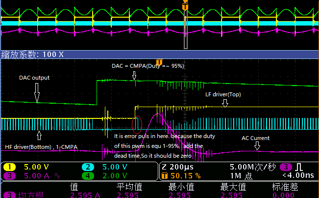
1:Waveform

The 4th Channel:  DAC output according to variable "PFC_Duty" .  It is correct in Red circle position.

The 1st Channel:  PWM output according to variable "PFC_Duty" .  It is incorrect in Red circle position.

The 2nd Channel:  PWM complementary output with 1st channel . It is incorrect in Red circle position.

2. Source code

interrupt void ISR4(void)   ----->is called every 14.92us
{
    EINT;

     Grid_Vols = (float)PFC_V_GRID_ADCREAD - 2505.0f;
    Grid_Vols = Grid_Vols * .42228;//.39196; //.4259;//.3;  // Scale to real world volts

    CLA_forceTasks(CLA1_BASE,CLA_TASKFLAG_2);       ----->To trigger task 2 in CLA

   ....

 
  DAC_Output_Val = (DAC_Output[4]*0.0000152587890625)*5;
  DAC_setShadowValue(DACA_BASE, DAC_Output_Val);

}    ------>about 5us for this routine

static inline void CLA_TASK2(void)

{

    ....

   cla_temp =(uint32_t)(PFC_Duty*65536.0);
   DAC_Output[4]=cla_temp;
   HWREG(PFC_LEG1_PWM_BASE + HRPWM_O_CMPA) = cla_temp;
   cla_temp = (uint32_t)(PFCDB*65536.0);
   HWREG(PFC_LEG1_PWM_BASE + HRPWM_O_DBREDHR) = cla_temp;
   HWREG(PFC_LEG1_PWM_BASE + HRPWM_O_DBFEDHR) = cla_temp;

}   ------>about 13us for this routine

Please help advise the possibilities. Thanks.

  • If you use complimentary PWM you cannot write CMPA equal to zero, you should clamp it to be 1 min to avoid glitches like these.

    The DBRED and DBFED will anyways eat up that pulse and you will not see the PWM , but while transitioning if you do not hedge against it you can see these type of glicthes.

    Alternatively, a more detailed review of PWM configuration can find the root cause,

    -Manish 

  • Manish Bhardwaj said:

    If you use complimentary PWM you cannot write CMPA equal to zero, you should clamp it to be 1 min to avoid glitches like these.

    The DBRED and DBFED will anyways eat up that pulse and you will not see the PWM , but while transitioning if you do not hedge against it you can see these type of glicthes.

    Alternatively, a more detailed review of PWM configuration can find the root cause,

    -Manish 

    Hi Manish,

    as you said, I already did (please refer to the source code as below). In this switch period at Red circle position, the PWM should write CMPA equal to approximate 100% of period. in the waveform figure,the duty of PWM(Yellow channel) should be equal to approximate 100% , rather than 0%. in addition,The value of variable " PFC_Duty",  be written to the CMPA and DAC in two  switch periods differently. but the result is: the DAC output is correct, the PWM output is incorrect.

    Thank you for your support.

    static inline void CLA_TASK2(void)

    {

        ....


      if (PFC_Duty<=1.0f)
        PFC_Duty=1;

       if (PFC_Duty>=(float)Tc)
        PFC_Duty=(float)Tc-1.0f;

       cla_temp =(uint32_t)(PFC_Duty*65536.0);
       DAC_Output[4]=cla_temp;
       HWREG(PFC_LEG1_PWM_BASE + HRPWM_O_CMPA) = cla_temp;
       cla_temp = (uint32_t)(PFCDB*65536.0);
       HWREG(PFC_LEG1_PWM_BASE + HRPWM_O_DBREDHR) = cla_temp;
       HWREG(PFC_LEG1_PWM_BASE + HRPWM_O_DBFEDHR) = cla_temp;

    }   ------>about 13us for this routine

  • I am not sure if I can debug the code like this, 

    we do have Totempole PFC solutions

    Please refer to the code in the SDK, 

    we do have an open bug in that code that it is missing the guards for the PWM. 

    Also to change the duty cycle, you should use a state machine to reduce the zero-crossing distortion, you can look as to how we handle it in the SDK code. 

    Basically you will be transitioning from a 0 to full duty cycle if you do the above method. 

    https://www.ti.com/tool/C2000WARE-DIGITALPOWER-SDK

  • Hi Manish,

           Thank you for your support!

           For this issue,  It is seem that the shadow mode of CMPA(EPWM1) is unstable.  What do you think?. See details below:

           * Active Counter-Compare A (CMPA) load from Shadow on CTR= ZERO. 

    • SOURCE CODE

      interrupt void ISR4(void)    

      {

          ……

          //Read from CMPA,and post to DAC

    DAC_Output_Val = HWREG(PFC_LEG1_PWM_BASE + HRPWM_O_CMPA)*0.0000152587890625*5;

    DAC_setShadowValue(DACA_BASE, DAC_Output_Val);

    }

               __attribute__((interrupt))  void Cla1Task2 ( void )


                       ……

    cla_temp =(uint32_t)(PFC_Duty*65536.0);

                 HWREG(PFC_LEG1_PWM_BASE + HRPWM_O_CMPA) = cla_temp;

                 cla_temp = (uint32_t)(PFCDB*65536.0);

                  HWREG(PFC_LEG1_PWM_BASE + HRPWM_O_DBREDHR) = cla_temp;

                  HWREG(PFC_LEG1_PWM_BASE + HRPWM_O_DBFEDHR) = cla_temp;


        * The timing of ISR4 and Cla1Task2


    * The waveform of DAC output and PWM output


  • Hi,

    There are certain notes in the device TRM chapter 18.6.5 Waveforms for Common Configurations.
    Please review these conditions and make sure they are addressed accordingly - particularly if you are targeting 0-100% duty cycle.
    There is also a application note in the same section on PWM waveform generation for 0-100% duty.

  • Hi Subrahmanya,

    Thanks!

    It is seem this issue has been resolved. system is operating normally for a long time. please refer to below source code, the red code is modifying code. but I can not understand why  it is ok after modified below code. In addition, "Tc-2" is not ok also.

     if (PFC_Duty<=1.0f)
        PFC_Duty=1;

            //if (PFC_Duty>=(float)Tc)
          // PFC_Duty=(float)Tc - 1.0f;
       if (PFC_Duty>=(float)Tc-3)
          PFC_Duty=(float)Tc-3.0f;

        cla_temp =(uint32_t)(PFC_Duty*65536.0);
       DAC_Output[4]=cla_temp;
        HWREG(PFC_LEG1_PWM_BASE + HRPWM_O_CMPA) = cla_temp;
       cla_temp = (uint32_t)(PFCDB*65536.0);
       DAC_Output[7] = cla_temp;
       HWREG(PFC_LEG1_PWM_BASE + HRPWM_O_DBREDHR) = cla_temp;
       HWREG(PFC_LEG1_PWM_BASE + HRPWM_O_DBFEDHR) = cla_temp;

    PWM configuration:

    * UP-Down mode

    * PWM CLOCK = 100M

    * TBPRD = 746 (about 67KHz)

    * DBFED=DBRED = 55(550ns)

    * load CMPA  from shadow at CRT=0

    * load DBFED /DBRED  from shadow at CRT=0

    TC = 746, It is a fixed value

  • Hi.

    Great to know that your issue is resolved.

    So you are limiting the duty to maximum of period-3. Is this correct?
    Is this because you are using high resolution PWM? If you are using high resolution mode - there is a limitation on edge placement for 3 cycles around the period and zero events.