This thread has been locked.

If you have a related question, please click the "Ask a related question" button in the top right corner. The newly created question will be automatically linked to this question.

TMS320F28388D: Current overshoot on MOSFET switch in motor phase using DRV8323RS

Part Number: TMS320F28388D
Other Parts Discussed in Thread: DRV8323, BOOSTXL-DRV8323RS, TMDSCNCD28388D

Hello,

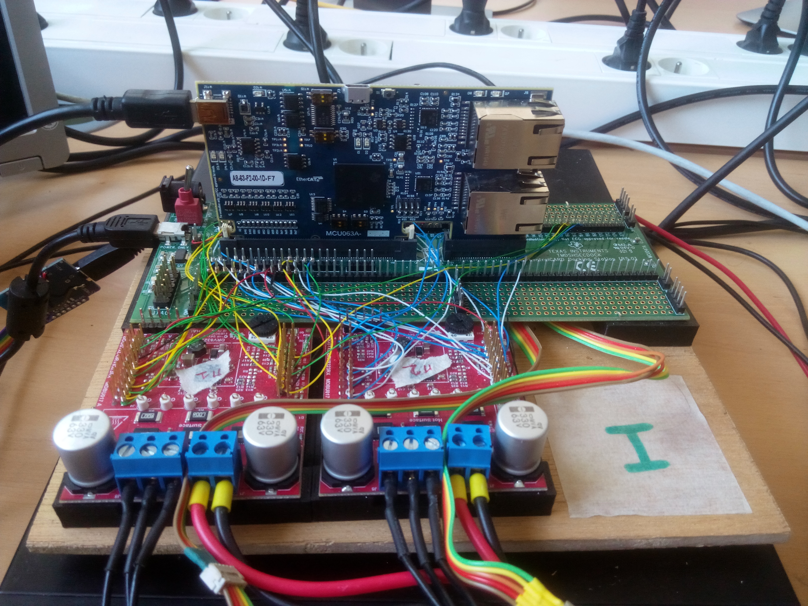
We are currently implementing FOC using both TMS320F28388D and DRV8323RS gate to control PMSM motors.
But when we look at the currents we clearly see a current overshoot that can become a problem in certain cases.

Here it is:

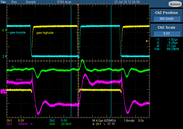
The different channels are:

Yellow: Gate High side PWM

Blue; Gate Low side PWM

Green; Real phase current (measured thanks to a current probe)

Purple: DRV ISENA pin (filtered current sense pin)

We see here that each time the transistors are switching, an overshoot or an undershoot occurs in the motor phases.

However the current should remain constant because of the induction of the motor phase.

Also, the undershoot over the low side shunt resistor shouldn't happen when the low side transistor is open, the current should go to zero very quickly.

Here is the same measurement zoomed on the transition:

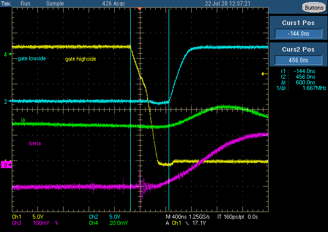
Do you have an idea of what is causing this ?

Thanks in advance.

  • Hi,

    Did you measure the gate low side/high side by using differential scope from gate-source terminal of the switching device?

    How much deadtime did you apply? (DBRED and DBFED) I clearly see the body diode conduction period on the zoom-in picture but can not see it in the first picture.

    Best,

    John

  • Hi John thanks for your answer.

    We measured the gate low side/high side by measuring the voltage between ground and the pwm signal pin. That's why the high side and the low side aren't at the same scale.

    The dead time is handled by the DRV8323 and is set at 100ns. The PWM sent by the control card doesn't have a dead band since the DRV is adds one. Do you think that the control card should also add a dead time ?

    Best regards,
    Natan

  • Natan,

    Can you increase the dead time setting on DRV8323? If this does not work, We may need help from motor drive forum experts.

    Best,

    John

  • Hi John, thanks for your answer.


    I tried DRV deadtime settings between 50 and 200ns and the overshoot increases.

    It goes from around 50% for a 50ns deadtime and a bit over 60% for a 200ns deadtime.

    Best,

    Natan

  • Hi Nathan,

    Are you refer ringing of isena? If so that seemingly is occurring from excessive heal undershoot in both switches. Undershoot heals are typically due to gate drive resistance, not always. Your first capture seems to indicate the heals are the culprit of both sides. It may be high side undershoot is affecting bus voltage too, thus effecting the low side turn on events in a bad way. PCB must have ample local DC filter capacitor, perhaps one way to reduce power supply drooping in both events.

  • Natan,

    We would need to see your schematic and layout to dig into this further.

    Regards,

    -Adam

  • Hi Adam, thanks for your answer.

    Our setup is very simple. We are using a TMDSCNCD28388D control card with two BOOSTXL-DRV8323RS motor drivers.

    The drivers are controlling T-Motor Antigravity4004 300kv motors.

    The power supply of the control card is a regular USB cable, and the motor drivers supply is an external 12V power supply.

    (Also, there are encoders to measure the rotor angle).

    Here is a picture of the setup:

    Also, here is the pin assignment file of the montage:

    PinAssignment.zip

    Best,
    Natan

  • Hi Gl, thanks for your answer.

    What do you mean exactly by "heal" ?

    Bus voltage is something we haven't checked yet. I'm going to dig a bit in this direction. Thanks.

    Best,

    Natan

  • Natan,

    Please post your findings in this thread.

    Regards,

    -Adam

  • Ok sorry,

    My last findings was that the Vbus measurement shew a 1 or 2 V peak to peak disturbances (with a 12V supply voltage), during a very short period of time. So it seems that much of an issue, maybe I'm wrong.

    Also I wanted to add that the motor characteristics are:

    Motor: Tmotor antigravity4004 kv300

    Measured resistance between two phases: 0.65 Ohm

    Measured inductance between two phases: 270 uH

  • Hi Adam,

    After doing some more tests, it seems that the overshoot isn't occuring in the motor phase. We had a false measurement because the current probe was just next to a motor, so we think that the magnetic field generated by the motor was measured by the probe.

    Here is a screen of the new measurements

    Also, the noise level we see here is the one we have when the probe isn't measuring any current.

    Best
    Natan